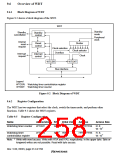
9.8
Using the WDT
9.8.1
Canceling Standby
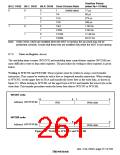
The WDT can be used to cancel standby mode with an NMI or other interrupt. The procedure is
described below. (The WDT does not run when a reset is used for canceling, so keep the RESET
pin low until the clock stabilizes.)
1. Before transitioning to standby mode, always clear the TME bit in WTCSR to 0. When the
TME bit is 1, an erroneous reset or interval timer interrupt may be generated when the count
overflows.
2. Set the type of count clock used in the CKS2–CKS0 bits in WTCSR and the initial values for
the counter in the WTCNT counter. These values should ensure that the time till count
overflow is longer than the clock oscillation settling time.
3. Switch to standby mode by executing a SLEEP instruction to stop the clock.
4. The WDT starts counting by detecting the edge change of the NMI signal or detecting
interrupts.
5. When the WDT count overflows, the CPG starts supplying the clock and the processor
resumes operation. The WOVF flag in WTCSR is not set when this happens.
6. Since the WDT continues counting from H'00, set the STBY bit in the STBCR register to 0 in
the interrupt handling routine and this will stop the WDT. When the STBY bit remains at 1,
the SH7709S again enters standby mode when the WDT has counted up to H'80. This standby
mode can be canceled by a power-on reset.
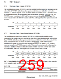
9.8.2
Changing the Frequency
To change the frequency used by the PLL, use the WDT. When changing the frequency only by
switching the divider, do not use the WDT.
1. Before changing the frequency, always clear the TME bit in WTCSR to 0. When the TME bit
is 1, an erroneous reset or interval timer interrupt may be generated when the count overflows.
2. Set the type of count clock used in the CKS2–CKS0 bits of WTCSR and the initial values for
the counter in the WTCNT counter. These values should ensure that the time till count
overflow is longer than the clock oscillation settling time.
3. When the frequency control register (FRQCR) is written to, the clock stops and the processor
enters standby mode temporarily. The WDT starts counting.
4. When the WDT count overflows, the CPG resumes supplying the clock and the processor
resumes operation. The WOVF flag in WTCSR is not set when this happens.
5. The counter stops at a value of H'00 or H'01. The stop value depends on the clock ratio.
Rev. 5.00, 09/03, page 218 of 760

 RENESAS [ RENESAS TECHNOLOGY CORP ]