9.6
Overview of WDT
9.6.1
Block Diagram of WDT
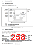
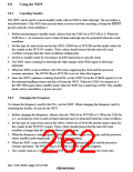
Figure 9.2 shows a block diagram of the WDT.
WDT
Standby
mode
Standby
cancellation
Standby
control
Peripheral
clock
Internal
reset
request
Reset
control
Divider
Clock selection
Overflow
Clock selector
Clock
Interrupt
request
Interrupt
control
WTCSR
WTCNT
Bus interface
Legend
WTCSR: Watchdog timer control/status register
WTCNT: Watchdog timer counter
Figure 9.2 Block Diagram of WDT
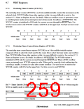
Register Configuration
9.6.2
The WDT has two registers that select the clock, switch the timer mode, and perform other
functions. Table 9.5 shows the WDT registers.
Table 9.5 Register Configuration
Name
Abbreviation R/W Initial Value Address
Access Size
*
R/W H'00
Watchdog timer counter
WTCNT
H'FFFFFF84 R: 8;
*
*
W: 16
*
Watchdog timer
control/status register
WTCSR
R/W H'00
H'FFFFFF86 R: 8;
W: 16
Note: * Write with word access. Write with H'5A and H'A5, respectively, in the upper byte. Byte or
longword writes are not possible. Read with byte access.
Rev. 5.00, 09/03, page 214 of 760

 RENESAS [ RENESAS TECHNOLOGY CORP ]