When the following three conditions are all met, FRQCR should not be changed while a DMAC
transfer is in progress.
•
•
•
Bits IFC2 to IFC0 are changed.
STC2 to STC0 are not changed.
The clock ratio of Iφ (on-chip clock) to Bφ (bus clock) after the change is other than 1:1.
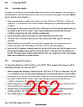
9.8.3
Using Watchdog Timer Mode
1. Set the WT/IT bit in the WTCSR register to 1, set the reset type in the RSTS bit, set the type of
count clock in the CKS2–CKS0 bits, and set the initial value of the counter in the WTCNT
counter.
2. Set the TME bit in WTCSR to 1 to start the count in watchdog timer mode.
3. While operating in watchdog timer mode, rewrite the counter periodically to H'00 to prevent
the counter from overflowing.
4. When the counter overflows, the WDT sets the WOVF flag in WTCSR to 1 and generates the
type of reset specified by the RSTS bit. The counter then resumes counting. When a reset is
generated, a low level is output at the RESETOUT pin, and a high level at the STATUS0 and
STATUS1 pins. The output period is approximately 1 count clock cycle in the case of a power-
on reset, and approximately 5 peripheral clock cycles in the case of a manual reset.
9.8.4
Using Interval Timer Mode
When operating in interval timer mode, interval timer interrupts are generated at every overflow of
the counter. This enables interrupts to be generated at set periods.
1. Clear the WT/IT bit in the WTCSR register to 0, set the type of count clock in the CKS2–
CKS0 bits, and set the initial value of the counter in the WTCNT counter.
2. Set the TME bit in WTCSR to 1 to start the count in interval timer mode.
3. When the counter overflows, the WDT sets the IOVF flag in WTCSR to 1 and an interval
timer interrupt request is sent to the INTC. The counter then resumes counting.
Rev. 5.00, 09/03, page 219 of 760

 RENESAS [ RENESAS TECHNOLOGY CORP ]