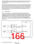
6.2.4
PINT Interrupts
PINT interrupts are input by level from pins PINT0–PINT15. The priority level can be set by
interrupt priority register D (IPRD) in a range from 0 to 15, in groups of PINT0–PINT7 and
PINT8–PINT15.
The PINT0/1 interrupt level should be held until the interrupt is accepted and interrupt handling is
started. Correct operation cannot be guaranteed if the level is not maintained.
The interrupt mask bits (I3–I0) in the status register (SR) are not affected by PINT interrupt
handling.
PINT0/1 interrupts can wake the chip up from the standby state when the relevant interrupt level is
higher than the setting of I3–I0 in the SR register (but only when the RTC 32-kHz oscillator is
used).
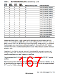
6.2.5
On-Chip Peripheral Module Interrupts
On-chip peripheral module interrupts are generated by the following ten modules:
•
•
•
•
•
•
•
•
Timer unit (TMU)
Realtime clock (RTC)
Serial communication interfaces (SCI, IrDA, SCIF)
Bus state controller (BSC)
Watchdog timer (WDT)
Direct memory access controller (DMAC)
Analog-to-digital converter (ADC)
User-debugging interface (UDI)
Not every interrupt source is assigned a different interrupt vector. Sources are reflected in the
interrupt event registers (INTEVT and INTEVT2). It is easy to identify sources by using the value
of the INTEVT or INTEVT2 register as a branch offset.
A priority level (from 0 to 15) can be set for each module except UDI by writing to interrupt
priority registers A, B, and E (IPRA, IPRB, and IPRE). The priority level of the UDI interrupt is
15 (fixed).
The interrupt mask bits (I3–I0) in the status register are not affected by on-chip peripheral module
interrupt handling.
TMU and RTC interrupts can wake the chip up from the standby state when the relevant interrupt
level is higher than the setting of I3–I0 in the SR register (but only when the RTC 32-kHz
oscillator is used).
Rev. 5.00, 09/03, page 124 of 760

 RENESAS [ RENESAS TECHNOLOGY CORP ]