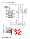
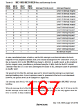
6.2
Interrupt Sources
There are five types of interrupt sources: NMI, IRQ, IRL,PINT, and on-chip peripheral modules.
Each interrupt has a priority level (0–16), with 0 the lowest and 16 the highest. Priority level 0
masks an interrupt.
6.2.1
NMI Interrupt
The NMI interrupt has the highest priority level of 16. When the BLMSK bit in the interrupt
control register (ICR1) is 1 or the BL bit in the status register (SR) is 0, NMI interrupts are
accepted when the MAI bit in the ICR1 register is 0. NMI interrupts are edge-detected. In sleep or
standby mode, the interrupt is accepted regardless of the BL setting. The NMI edge select bit
(NMIE) in the interrupt control register 0 (ICR0) is used to select either rising or falling edge
detection. When the NMIE bit in the ICR0 register is changed, an NMI interrupt is not detected for
20 cycles after changing ICR0. NMIE to avoid a false detection of NMI. NMI interrupt exception
handling does not affect the interrupt mask level bits (I3–I0) in the status register (SR).
When the BL bit is land the BLMSK bit in the ICR1 register is set to 1 and only NMI interrupts
are accepted, the SPC register and SSR register are updated by the NMI interrupt handler, making
it impossible to return to the original processing from exception handling initiated prior to the
NMI interrupt. Use should therefore be restricted to cases where return is not necessary.
It is possible to wake the chip up from the standby state with an NMI interrupt (except when the
MAI bit in the ICR1 register is set to 1).
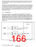
6.2.2
IRQ Interrupts
IRQ interrupts are input by level or edge from pins IRQ0–IRQ5. The priority level can be set by
interrupt priority registers C–D (IPRC–IPRD) in a range from 0 to 15.
When using edge-sensing for IRQ interrupts, clear the interrupt source by having software read 1
from the corresponding bit in IRR0, then write 0 to the bit.
When the ICR1 register is rewritten, IRQ interrupts may be mistakenly detected, depending on the
pin states. To prevent this, rewrite the register while interrupts are masked, then release the mask
after clearing the illegal interrupt by writing 0 to interrupt request register 0 (IRR0).
Edge input interrupt detection requires input of a pulse width of more than two cycles on a
peripheral clock (Pφ) basis.
The interrupt mask bits (I3–I0) in the status register (SR) are not affected by IRQ interrupt
handling.
Rev. 5.00, 09/03, page 121 of 760

 RENESAS [ RENESAS TECHNOLOGY CORP ]