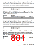
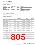
19.1.3 Pin Configuration
Table 19.1 shows the INTC pin configuration.
Table 19.1 INTC Pins
Pin Name
Abbreviation
I/O
Function
Nonmaskable interrupt
input pin
NMI
Input
Input of nonmaskable interrupt request
signal
Interrupt input pins
Input
Input of interrupt request signals
(maskable by I3–I0 in SR)
,5/6–,5/3
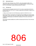
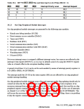
19.1.4 Register Configuration
The INTC has the registers shown in table 19.2.
Table 19.2 INTC Registers
1
*
Initial Value
Area 7
P4 Address Address
Access
Size
Name
Abbreviation
R/W
2
*
Interrupt control ICR
register
R/W
H'FFD00000 H'1FD00000 16
H'FFD00004 H'1FD00004 16
H'FFD00008 H'1FD00008 16
H'FFD0000C H'1FD0000C 16
H'FFD00010 H'1FD00010 16
Interrupt priority IPRA
register A
R/W
R/W
R/W
R/W
R/W
H'0000
H'0000
H'0000
H'DA74
Interrupt priority IPRB
register B
Interrupt priority IPRC
register C
Interrupt priority IPRD
3
*
register D
Interrupt priority INTPRI00
H'00000000 H'FE080000 H'1E080000
32
level setting
4
*
register 00
Interrupt source INTREQ00
R
H'00000000 H'FE080020 H'1E080020
H'00000300 H'FE080040 H'1E080040
32
32
32
4
*
register 00
Interrupt mask
INTMSK00
R/W
R
4
*
register 00
Interrupt mask
clear register 00
INTMSKCLR00
—
H'FE080060 H'1E080060
4
*
Notes: *1 Initialized by a power-on reset or manual reset.
*2 H'8000 when the NMI pin is high, H'0000 when the NMI pin is low.
*3 SH7750S and SH7750R only
*4 SH7750R only
Rev. 6.0, 07/02, page 753 of 986

 RENESAS [ RENESAS TECHNOLOGY CORP ]