17.3.6
Data Transmit/Receive Operations
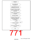
Initialization: Before transmitting and receiving data, the smart card interface must be initialized
as described below. Initialization is also necessary when switching from transmit mode to receive
mode, or vice versa. Figure 17.7 shows a sample initialization processing flowchart.
1. Clear the TE and RE bits in the serial control register (SCSCR1) to 0.
2. Clear error flags FER/ERS, PER, and ORER in the serial status register (SCSSR1) to 0.
3. Set the GM bit, parity bit (O/(), and baud rate generator select bits (CKS1 and CKS0) in the
serial mode register (SCSMR1). Clear the CHR and MP bits to 0, and set the STOP and PE
bits to 1.
4. Set the SMIF, SDIR, and SINV bits in the smart card mode register (SCSCMR1).
When the SMIF bit is set to 1, the TxD pin and RxD pin both go to the high-impedance state.
5. Set the value corresponding to the bit rate in the bit rate register (SCBRR1).
6. Set the clock source select bits (CKE1 and CKE0) in SCSCR1. Clear the TIE, RIE, TE, RE,
MPIE, and TEIE bits to 0.
If the CKE0 bit is set to 1, the clock is output from the SCK pin.
7. Wait at least one bit interval, then set the TIE, RIE, TE, and RE bits in SCSCR1. Do not set the
TE bit and RE bit at the same time, except for self-diagnosis.
Rev. 6.0, 07/02, page 718 of 986

 RENESAS [ RENESAS TECHNOLOGY CORP ]