16.3
Operation
16.3.1 Overview
The SCIF can carry out serial communication in asynchronous mode, in which synchronization is
achieved character by character. See section 15.3.2, Operation in Asynchronous Mode, for details.
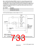
Sixteen-stage FIFO buffers are provided for both transmission and reception, reducing the CPU
overhead and enabling fast, continuous communication to be performed. 5765 and &765 signals
are also provided as modem control signals.
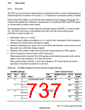
The transmission format is selected using the serial mode register (SCSMR2), as shown in table
16.3. The SCIF clock source is determined by the CKE1 bit in the serial control register
(SCSCR2), as shown in table 16.4.
•
•
Data length: Choice of 7 or 8 bits
Choice of parity addition and addition of 1 or 2 stop bits (the combination of these parameters
determines the transfer format and character length)
•
Detection of framing errors, parity errors, receive-FIFO-data-full state, overrun errors, receive-
data-ready state, and breaks, during reception
•
•
Indication of the number of data bytes stored in the transmit and receive FIFO registers
Choice of internal or external clock as SCIF clock source
When internal clock is selected: The SCIF operates on the baud rate generator clock, and can
output a clock with a frequency of 16 times the bit rate.
When external clock is selected: A clock with a frequency of 16 times the bit rate must be
input (the on-chip baud rate generator is not used).
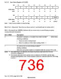
Table 16.3 SCSMR2 Settings for Serial Transfer Format Selection
SCSMR2 Settings SCIF Transfer Format
Multiprocessor Parity Stop Bit
Bit 6:
CHR
Bit 5:
PE
Bit 3:
STOP Mode
Data
Length
Bit
Bit
Length
0
0
1
0
1
0
1
0
1
0
1
0
1
Asynchronous mode 8-bit data No
No
1 bit
2 bits
1 bit
Yes
No
2 bits
1 bit
1
7-bit data
2 bits
1 bit
Yes
2 bits
Rev. 6.0, 07/02, page 685 of 986

 RENESAS [ RENESAS TECHNOLOGY CORP ]