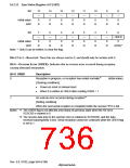
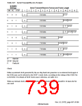
Table 16.5 Serial Transmit/Receive Formats
SCSMR2
Settings
Serial Transmit/Receive Format and Frame Length
CHR PE STOP
1
2
3
4
5
6
7
8
9
10
11
12
0
0
0
0
1
1
1
0
0
1
1
0
0
1
1
0
1
0
1
0
1
0
S
8-bit data
STOP
S
S
S
S
S
S
S
8-bit data
8-bit data
8-bit data
7-bit data
7-bit data
7-bit data
7-bit data
STOP STOP
P
P
STOP
STOP STOP
STOP
STOP STOP
P
P
STOP
1
1
STOP STOP
S:
Start bit
STOP: Stop bit
P:
Parity bit
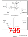
Clock
Either an internal clock generated by the on-chip baud rate generator or an external clock input at
the SCK2 pin can be selected as the SCIF’s serial clock, according to the setting of the CKE1 bit
in SCSCR2. For details of SCIF clock source selection, see table 16.4.
When an external clock is input at the SCK2 pin, the clock frequency should be 16 times the bit
rate used.
Rev. 6.0, 07/02, page 687 of 986

 RENESAS [ RENESAS TECHNOLOGY CORP ]