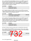
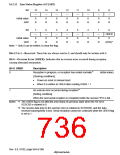
Bit 0—Serial Port Break Data (SPB2DT): Specifies the serial port RxD2 pin input data and
TxD2 pin output data. The TxD2 pin output condition is specified by the SPB2IO bit (see the
description of bit 1, SPB2IO, for details). When the TxD2 pin is designated as an output, the value
of the SPB2DT bit is output to the TxD2 pin. The RxD2 pin value is read from the SPB2DT bit
regardless of the value of the SPB2IO bit. The initial value of this bit after a power-on reset or
manual reset is undefined.
Bit 0: SPB2DT
Description
0
1
Input/output data is low-level
Input/output data is high-level
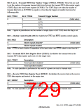
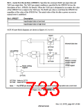
SCIF I/O port block diagrams are shown in figures 16.2 to 16.5.
Reset
R
D7
D6
Q
D
RTSIO
C
Internal data bus
SPTRW
Reset
MD8/
R
Q
D
RTSDT
C
SCIF
Modem control
enable signal*
SPTRW
signal
Mode setting
register
SPTRR
SPTRW: Write to SPTR
SPTRR: Read SPTR
Note: * The
pin function is designated as modem control by the MCE bit in SCFCR2.
Figure 16.2 MD8/5765 Pin
Rev. 6.0, 07/02, page 681 of 986

 RENESAS [ RENESAS TECHNOLOGY CORP ]