Bits 14 to 10—Reserved: These bits are always read as 0, and should only be written with 0.
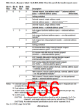
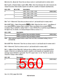
Bits 9 and 8—Priority Mode 1 and 0 (PR1, PR0): These bits determine the order of priority for
channel execution when transfer requests are made for a number of channels simultaneously.
Bit 9: PR1
Bit 8: PR0
Description
0
0
1
0
1
CH0 > CH1 > CH2 > CH3
CH0 > CH2 > CH3 > CH1
CH2 > CH0 > CH1 > CH3
Round robin mode
(Initial value)
1
Bits 7 to 5—Reserved: These bits are always read as 0, and should only be written with 0.
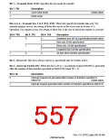
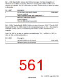
Bit 4 (SH7750S)—Check Overrun for '5(4 (COD): When this bit is set to 1, cancellation of
an accepted '5(4 acceptance flag is enabled. When cancellation of an accepted '5(4
acceptance flag is enabled by setting COD to 1, clear CHCRn.DS to 0 and then negate '5(4 (to
the high level). For details, see External Request Mode in section 14.3.2.
Bit 4: COD
Description
0
1
'5(4 acceptance flag cancellation disabled
'5(4 acceptance flag cancellation enabled
(Initial value)
Note: When external request mode is used in the SH7750S, recommend setting COD to 1
permanently.
Bit 4 (SH7750)—Reserved: These bits are always read as 0, and should only be written with 0.
Bit 3—Reserved: This bit is always read as 0, and should only be written with 0.
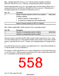
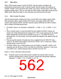
Bit 2—Address Error Flag (AE): Indicates that an address error has occurred during DMA
transfer. If this bit is set during data transfer, transfers on all channels are suspended, and an
interrupt request (DMAE) is generated. The CPU cannot write 1 to AE. This bit can only be
cleared by writing 0 after reading 1.
Bit 2: AE
Description
0
No address error, DMA transfer enabled
(Initial value)
[Clearing condition]
When 0 is written to AE after reading AE = 1
1
Address error, DMA transfer disabled
[Setting condition]
When an address error is caused by the DMAC
Rev. 6.0, 07/02, page 508 of 986

 RENESAS [ RENESAS TECHNOLOGY CORP ]