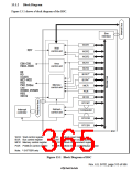
13.1.2 Block Diagram
Figure 13.1 shows a block diagram of the BSC.
Bus
interface
WCR1
Wait
control unit
WCR2
WCR3
BCR1
BCR2
Area
control unit
–
–
*
BCR3
BCR4
RD/
*
–
Memory
control unit
,
MCR
PCR
CKE
,
RFCR
RTCNT
Refresh
control unit
Interrupt
controller
Comparator
RTCOR
RTCSR
BSC
WCR: Wait control register
BCR: Bus control register
MCR: Memory control register
PCR: PCMCIA control register
RFCR: Refresh count register
RTCNT: Refresh timer count register
RTCOR: Refresh time constant register
RTCSR: Refresh timer control/status register
Note: * SH7750R only
Figure 13.1 Block Diagram of BSC
Rev. 6.0, 07/02, page 313 of 986

 RENESAS [ RENESAS TECHNOLOGY CORP ]