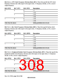
10.7.2 Register Configuration
The WDT has the two registers summarized in table 10.5. These registers control clock selection
and timer mode switching.
Table 10.5 WDT Registers
Initial
Value
Area 7
P4 Address Address
Name
Abbreviation R/W
Access Size
Watchdog timer
counter
WTCNT
R/W* H'00
H'FFC00008 H'1FC00008 R: 8, W: 16*
H'FFC0000C H'1FC0000C R: 8, W: 16*
Watchdog timer
control/status
register
WTCSR
R/W* H'00
Note: * Use word-size access when writing. Perform the write with the upper byte set to H'5A or
H'A5, respectively. Byte- and longword-size writes cannot be used.
Use byte access when reading.
10.8
WDT Register Descriptions
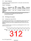
10.8.1 Watchdog Timer Counter (WTCNT)
The watchdog timer counter (WTCNT) is an 8-bit readable/writable counter that counts up on the
selected clock. When WTCNT overflows, a reset is generated in watchdog timer mode, or an
interrupt in interval timer mode. WTCNT is initialized to H'00 only by a power-on reset via the
5(6(7 pin.
To write to the WTCNT counter, use a word-size access with the upper byte set to H'5A. To read
WTCNT, use a byte-size access.
Bit:
7
6
5
4
3
2
1
0
Initial value:
R/W:
0
0
0
0
0
0
0
0
R/W
R/W
R/W
R/W
R/W
R/W
R/W
R/W
Rev. 6.0, 07/02, page 260 of 986

 RENESAS [ RENESAS TECHNOLOGY CORP ]