4. The WDT starts counting on detection of an NMI signal transition edge or an interrupt.
5. When the WDT count overflows, the CPG starts clock supply and the processor resumes
operation. The WOVF flag in the WTCSR register is not set at this time.
6. The counter stops at a value of H'00–H'01. The value at which the counter stops depends on
the clock ratio.
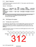
10.9.2 Frequency Changing Procedure
The WDT is used in a frequency change using the PLL. It is not used when the frequency is
changed simply by making a frequency divider switch.
1. Be sure to clear the TME bit in the WTCSR register to 0 before making a frequency change. If
the TME bit is set to 1, an inadvertent reset or interval timer interrupt may be caused when the
count overflows.
2. Select the count clock to be used with bits CKS2–CKS0 in the WTCSR register, and set the
initial value in the WTCNT counter. Make these settings so that the time until the count
overflows is at least as long as the clock oscillation stabilization time. For details of the clock
oscillation stabilization time, see section 22.3.1, Clock and Control Signal Timing.
3. When the frequency control register (FRQCR) is modified, the clock stops, and the standby
state is entered temporarily. The WDT starts counting.
4. When the WDT count overflows, the CPG starts clock supply and the processor resumes
operation. The WOVF flag in the WTCSR register is not set at this time.
5. The counter stops at a value of H'00–H'01. The value at which the counter stops depends on
the clock ratio.
6. When re-setting WTCNT immediately after modifying the frequency control register
(FRQCR), first read the counter and confirm that its value is as described in step 5 above.
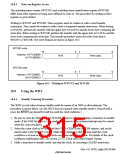
10.9.3 Using Watchdog Timer Mode
1. Set the WT/,7 bit in the WTCSR register to 1, select the type of reset with the RSTS bit, and
the count clock with bits CKS2–CKS0, and set the initial value in the WTCNT counter.
2. When the TME bit in the WTCSR register is set to 1, the count starts in watchdog timer mode.
3. During operation in watchdog timer mode, write H'00 to the counter periodically so that it does
not overflow.
4. When the counter overflows, the WDT sets the WOVF flag in the WTCSR register to 1, and
generates a reset of the type specified by the RSTS bit. The counter then continues counting.
Rev. 6.0, 07/02, page 264 of 986

 RENESAS [ RENESAS TECHNOLOGY CORP ]