10.8.3 Notes on Register Access
The watchdog timer counter (WTCNT) and watchdog timer control/status register (WTCSR)
differ from other registers in being more difficult to write to. The procedure for writing to these
registers is given below.
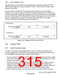
Writing to WTCNT and WTCSR: These registers must be written to with a word transfer
instruction. They cannot be written to with a byte or longword transfer instruction. When writing
to WTCNT, perform the transfer with the upper byte set to H'5A and the lower byte containing the
write data. When writing to WTCSR, perform the transfer with the upper byte set to H'A5 and the
lower byte containing the write data. This transfer procedure writes the lower byte data to
WTCNT or WTCSR. The write formats are shown in figure 10.3.
WTCNT write
15
8
7
0
Address: H'FFC00008
(H'1FC00008)
H'5A
Write data
Write data
WTCSR write
15
8
7
0
Address: H'FFC0000C
(H'1FC0000C)
H'A5
Figure 10.3 Writing to WTCNT and WTCSR
10.9
Using the WDT
10.9.1 Standby Clearing Procedure
The WDT is used when clearing standby mode by means of an NMI or other interrupt. The
procedure is shown below. (As the WDT does not operate when standby mode is cleared with a
reset, the 5(6(7 pin should be held low until the clock stabilizes.)
1. Be sure to clear the TME bit in the WTCSR register to 0 before making a transition to standby
mode. If the TME bit is set to 1, an inadvertent reset or interval timer interrupt may be caused
when the count overflows.
2. Select the count clock to be used with bits CKS2–CKS0 in the WTCSR register, and set the
initial value in the WTCNT counter. Make these settings so that the time until the count
overflows is at least as long as the clock oscillation stabilization time. For details of the clock
oscillation stabilization time, see section 22.3.1, Clock and Control Signal Timing.
3. Make a transition to standby mode, and stop the clock, by executing a SLEEP instruction.
Rev. 6.0, 07/02, page 263 of 986

 RENESAS [ RENESAS TECHNOLOGY CORP ]