9.4.2
Exit from Deep Sleep Mode
As with sleep mode, deep sleep mode is exited by means of an interrupt (NMI, IRL, or on-chip
peripheral module) or a reset.
9.5
Standby Mode
9.5.1
Transition to Standby Mode
If a SLEEP instruction is executed when the STBY bit in STBCR is set to 1, the chip switches
from the program execution state to standby mode. In standby mode, the on-chip peripheral
modules halt as well as the CPU. Clock output from the CKIO pin is also stopped.
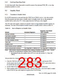
The CPU and cache register contents are retained. Some on-chip peripheral module registers are
initialized. The state of the peripheral module registers in standby mode is shown in table 9.4.
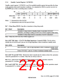
Table 9.4 State of Registers in Standby Mode
Registers That Retain
Module
Initialized Registers
Their Contents
Interrupt controller
User break controller
Bus state controller
On-chip oscillation circuits
Timer unit
—
All registers
—
All registers
—
All registers
—
All registers
TSTR register*
All registers except TSTR
All registers
Realtime clock
—
—
Direct memory access controller
Serial communication interface
All registers
See Appendix A, Address List See Appendix A, Address List
Notes: DMA transfer should be terminated before making a transition to standby mode. Transfer
results are not guaranteed if standby mode is entered during transfer.
*
Not initialized when the realtime clock (RTC) is in use (see section 12, Timer Unit
(TMU)).
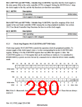
The procedure for a transition to standby mode is shown below.
1. Clear the TME bit in the WDT timer control register (WTCSR) to 0, and stop the WDT.
Set the initial value for the up-count in the WDT timer counter (WTCNT), and set the clock to
be used for the up-count in bits CKS2–CKS0 in the WTCSR register.
2. Set the STBY bit in the STBCR register to 1, then execute a SLEEP instruction.
3. When standby mode is entered and the chip’s internal clock stops, a low-level signal is output
at the STATUS1 pin, and a high-level signal at the STATUS0 pin.
Rev. 6.0, 07/02, page 231 of 986

 RENESAS [ RENESAS TECHNOLOGY CORP ]