9.7
Hardware Standby Mode (SH7750S, SH7750R Only)
9.7.1
Transition to Hardware Standby Mode
Setting the CA pin level low effects a transition to hardware standby mode. In this mode, all
modules other than the RTC stop, as in the standby mode selected using the SLEEP command.
Hardware standby mode differs from standby mode as follows:
1. Interrupts and manual resets are not available;
2. All output pins other than the STATUS pin are in the high-impedance state and the pull-up
resistance is off.
3. Even when no power is supplied to power pins other than the RTC power supply pin, the RTC
continues to operate.
The status of the STATUS pin is determined by the STHZ bit of STBCR2. See appendix E, Pin
Functions, for details of output pin states.
Operation when a low-level is input to the CA pin when in the standby mode depends on the CPG
status, as follows:
1. In standby mode
The clock remains stopped and a transition is made to the hardware standby state.
2. When WDT is operating when standby mode is exited by interrupt
Standby mode is momentarily exited, the CPU restarts, and then a transition is made to
hardware standby mode.
Note that the level of the CA pin must be kept low while in hardware standby mode.
9.7.2
Exit from Hardware Standby Mode
Hardware standby mode can only be exited by effecting a power-on reset.
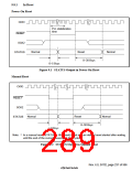
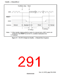
Setting the CA pin level high after the 5(6(7 pin level has been set low and the SCK2 pin high
starts the clock to oscillate. The 5(6(7 pin level should be kept low until the clock has stabilized,
then set high so that the CPU starts the power-on reset procedure.
Note that hardware standby mode cannot be exited using interrupts or a manual reset.
9.7.3
Usage Notes
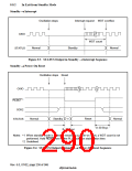
The CA pin level must be kept high during the power-on oscillation settling period when the RTC
power supply is started (figure 9.15).
Rev. 6.0, 07/02, page 235 of 986

 RENESAS [ RENESAS TECHNOLOGY CORP ]