Bit
Description
6
6
*
*
CSTP1
0
1
0
1
0
1
0
1
0
1
0
1
0
1
0
1
0
1
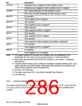
Peripheral clock is supplied to TMU channels 3 and 4
Peripheral clock supplied to TMU channels 3 and 4 is stopped
INTC detects interrupts on TMU channels 3 and 4
INTC does not detect interrupts on TMU channels 3 and 4
SQ operates
CSTP0
MSTP6
MSTP5
MSTP4
MSTP3
MSTP2
MSTP1
MSTP0
4
4
*
*
Clock supplied to SQ is stopped
UBC operates
5
*
Clock supplied to UBC is stopped
DMAC operates
3
*
Clock supplied to DMAC is stopped
SCIF operates
Clock supplied to SCIF is stopped
TMU operates
1
*
Clock supplied to TMU is stopped, and register is initialized
RTC operates
2
*
Clock supplied to RTC is stopped
SCI operates
Clock supplied to SCI is stopped
Notes: *1 The register initialized is the same as in standby mode, but initialization is not
performed if the RTC clock is not in use (see section 12, Timer Unit (TMU)).
*2 The counter operates when the START bit in RCR2 is 1 (see section 11, Realtime
Clock (RTC)).
*3 Terminate DMA transfers prior to making the transition to module standby mode. If you
make a transition to module standby mode while DMA transfers are in progress, the
results of those transfers cannot be guaranteed.
*4 SH7750S, SH7750R only
*5 For details, see section 20.6, User Break Controller Stop Functions.
*6 SH7750R only
9.6.2
Exit from Module Standby Function
The module standby function is exited by clearing the MSTP6–MSTP0, CSTP1, and CSTP0 bits
to 0, or by a power-on reset via the 5(6(7 pin or a power-on reset caused by watchdog timer
overflow.
Rev. 6.0, 07/02, page 234 of 986

 RENESAS [ RENESAS TECHNOLOGY CORP ]