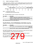
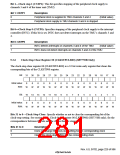
Bit 1—Clock stop 1 (CSTP1): This bit specifies stopping of the peripheral clock supply to
channels 3 and 4 of the timer unit (TMU).
Bit 1: CSTP1
Description
0
1
Peripheral clock is supplied to TMU channels 3 and 4
Peripheral clock supply to TMU channels 3 and 4 is stopped
(Initial value)
Bit 0 Clock Stop 0 (CSTP0): Specifies stopping of the peripheral clock supply to the interrupt
controller (INTC). If this bit is set, INTC does not detect interrupts on the TMU’s channels 3 and
4.
Bit 0: CSTP0
Description
0
1
INTC detects interrupts on channels 3 and 4 of the TMU
(Initial value)
INTC does not detect interrupts on channels 3 and 4 of the TMU
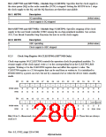
9.2.6
Clock-Stop Clear Register 00 (CLKSTPCLR00) (SH7750R Only)
The clock-stop clear register 00 (CLKSTPCLR00) is a 32-bit write-only register that clears the
corresponding bits of the CLKSTP00 register.
Bit:
31
30
29
28
27
26
25
24
23
22
21
20
19
18
17
16
Initial value:
R/W:
0
0
0
0
0
0
0
0
0
0
0
0
0
0
0
0
W
W
W
W
W
W
W
W
W
W
W
W
W
W
W
W
Bit:
15
14
13
12
11
10
9
8
7
6
5
4
3
2
1
0
Initial value:
R/W:
0
0
0
0
0
0
0
0
0
0
0
0
0
0
0
0
W
W
W
W
W
W
W
W
W
W
W
W
W
W
W
W
Bits 31 to 0 Clock-Stop Clear: Specify whether or not to clear the corresponding bit of the
clock-stop setting. See section 9.2.5, Clock-Stop Register 00 (LKSTP00) (SH7750R only), for the
correspondence between the bits and the clocks that are stopped.
Bits 31 to 0
Description
0
1
Does not change the clock-stop setting for the corresponding clock
Clears the clock-stop setting for the corresponding clock
Rev. 6.0, 07/02, page 229 of 986

 RENESAS [ RENESAS TECHNOLOGY CORP ]