APPENDIX
Appendix 7. Countermeasure against noise
4. Oscillator protection
The oscillator, which generates the basic clock for the microcomputer operations, must be protected from
the affect of other signals.
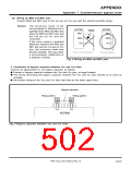
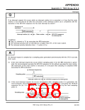
(1) Distance oscillator from signal lines with large current flows
Install the microcomputer, especially the oscillator, as far as possible from signal lines which handle
currents larger than the microcomputer current value tolerance.
Reason: The microcomputer is used in
systems which contain signal lines
for controlling motors, LEDs,
M37906
Mutual inductance
Large current
thermal heads, etc. Noise occurs
due to mutual inductance when a
large current flows through the signal
lines.
M
X
IN
X
OUT
Vss
Fig. 8 Wiring for signal lines where large current
flows
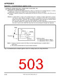
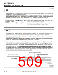
(2) Distance oscillator from signal lines with frequent potential level changes
ꢀ Install an oscillator and its wiring pattern away from signal lines where potential levels change
frequently.
ꢀ Do not cross these signal lines over the clock-related or noise-sensitive signal lines.
Reason: Signal lines with frequently changing
potential levels may affect other
signal lines at a rising or falling edge.
In particular, if the lines cross over
a clock-related signal line, clock
waveforms may be deformed, which
causes a microcomputer malfunction
or a program runaway.
M37906
Do not cross.
ꢀ
X
X
IN
OUT
V
SS
ꢀ I/O pin for signal with frequently
changing potential levels
Fig. 9 Wiring for signal lines where potential levels
frequently change
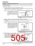
(3) Oscillator protection using Vss pattern
Print a Vss pattern on the bottom (soldering
side) of a double-sided printed circuit board,
under the oscillator mount position.
An example of Vss pattern on the
underside of an oscillator.
M37906
Mounted pattern
Connect the Vss pattern to the Vss pin of the
microcomputer with the shortest possible wiring,
separating it from other Vss patterns.
example of
oscillator unit.
XIN
X
OUT
Vss
Separate Vss lines for oscillation and supply.
Fig. 10 Vss pattern underneath mounted oscillator
7906 Group User’s Manual Rev.2.0
20-100

 RENESAS [ RENESAS TECHNOLOGY CORP ]