APPENDIX
Appendix 7. Countermeasure against noise
Appendix 7. Countermeasure against noise
General countermeasure examples against noise are described below. Although the effect of these
countermeasure depends on each system.
The user shall modify them according to the actual application and test them.
1. Short wiring length
The wiring on a printed circuit board may function as an antenna which feeds noise into the microcomputer.
The shorter the total wiring length (by mm unit), the less possibility of noise insertion into the microcomputer.
______
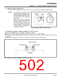
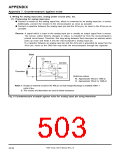
(1) Wiring for RESET pin
______
Make the length of wiring connected to the RESET pin as short as possible.
______
In particular, connect a capacitor between the RESET pin and the Vss pin with the shortest possible
wiring (within 20 mm).
______
Reason: If noise is input to the RESET pin, the microcomputer restarts operation before the internal
state of the microcomputer is completely initialized. This may cause a program runaway.
M37906
M37906
Noise
Reset
circuit
Reset
circuit
RESET
Vss
RESET
Vss
Vss
Vss
Not acceptable
Acceptable
______
Fig. 2 Wiring for RESET pin
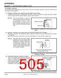
(2) Wiring for clock input/output pins
ꢀ Make the length of wiring connected to the clock input/output pins as short as possible.
ꢀ Make the length of wiring between the grounding lead of the capacitor, which is connected to
the oscillator, and the Vss pin of the microcomputer, as short as possible (within 20 mm).
ꢀ Separate the Vss pattern for oscillation from all other Vss patterns. (See Figure 10.)
Reason: The microcomputer’s operation
synchronizes with a clock generated
by the oscillation circuit.
If noise enters clock I/O pins, clock
waveforms may be deformed. This
Noise
M37906
M37906
may cause a malfunction or a
program runaway.
Also, if the noise causes a potential
difference between the Vss level of
the microcomputer and the Vss level
of an oscillator, the correct clock
w i l l n o t b e i n p u t i n t h e
microcomputer.
X
X
Vss
IN
X
IN
OUT
X
OUT
Vss
Not acceptable
Acceptable
Fig. 3 Wiring for clock input/output pins
7906 Group User’s Manual Rev.2.0
20-96

 RENESAS [ RENESAS TECHNOLOGY CORP ]