APPENDIX
Appendix 7. Countermeasure against noise
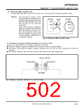
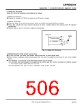
3. Wiring for analog input pins, analog power source pins, etc.
(1) Processing for analog input pins
ꢀ Connect a resistor to the analog signal line, which is connected to an analog input pin, in series.
Additionally, connect the resistor to the microcomputer as close as possible.
ꢀ Connect a capacitor between the analog input pin and the AVss pin, as close to the AVss pin as
possible.
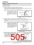
Reason: A signal which is input to the analog input pin is usually an output signal from a sensor.
The sensor, which detects changes in status, is installed far from the microcomputer’s
printed circuit board. Therefore, this long wiring between them becomes an antenna which
picks up noise and feeds it into the microcomputer’s analog input pin.
If a capacitor between an analog input pin and the AVss pin is grounded far away from the
AVss pin, noise on the GND line may enter the microcomputer through the capacitor.
Noise
(Note 2)
M37906
Acceptable
RI
AN
i
Thermistor
Acceptable
AVss
Not
acceptable
CI
Reference values
RI : Approximate 100 Ω to 1000 Ω
CI : Approximate 100 pF to 1000 pF
Notes 1: Design an external circuit for the ANi pin so that charge/discharge is available within 1
cycle of φAD
.
2: This resistor and thermistor are used to divide resistance.
Fig. 6 Countermeasure example against noise for analog input pin using thermistor
7906 Group User’s Manual Rev.2.0
20-98

 RENESAS [ RENESAS TECHNOLOGY CORP ]