APPENDIX
Appendix 7. Countermeasure against noise
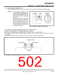
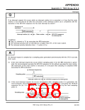
5. Setup for I/O ports
Setup I/O ports by hardware and software as follows:
<Hardware protection>
ꢀ Connect a resistor of 100 Ω or more to an I/O port in series.
<Software protection>
ꢀ Read the data of an input port several times to confirm that input levels are equal.
ꢀ Since the output data may reverse because of noise, rewrite data to the output port’s Pi register
periodically.
ꢀ Rewrite data to port Pi direction registers periodically.
Data bus
Noise
Direction register
Port latch
Port
Fig. 11 Setup for I/O ports
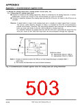
6. Reinforcement of the power source line
ꢀ For the Vss and Vcc lines, use thicker wiring than that of other signal lines.
ꢀ When using a multilayer printed circuit board, the Vss and Vcc patterns must each be one of the middle
layers.
ꢀ The following is necessary for double-sided printed circuit boards:
•On one side, the microcomputer is installed at the center, and the Vss line is looped or meshed around
it. The vacant area is filled with the Vss line.
•On the opposite side, the Vcc line is wired the same as the Vss line.
7906 Group User’s Manual Rev.2.0
20-101

 RENESAS [ RENESAS TECHNOLOGY CORP ]