A-D CONVERTER
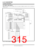
12.2 Block description
(1) Analog input pin select bits 0 (bits 0 to 2 at address 1E16), analog input pin select bits 1 (bits
3 to 0 at address DB16
)
These bits are used to select an analog input pin. Pins which are not selected as analog input pins
serve as programmable I/O port pins or I/O pins of other internal peripheral devices, which are
multiplexed.
When using pins AN
address DB16) to “0,” regardless of the A-D operation mode.
Pins AN to AN11 can be used only in the one-shot mode and repeat mode.
0
to AN , be sure to fix bit 3 of the analog input pin select bits 1 (bits 3 to 0 at
7
8
Also, these bits must be specified again if the user switches the operation mode to the one-shot
mode or repeat mode after the operation is performed in the single sweep mode, repeat sweep mode
0, or repeat sweep mode 1.
(2) A-D operation mode select bits 0 (bits 3 and 4 at address 1E16), A-D operation mode select bit
1 (bit 2 at address 1F16
)
These bits are used to select the operation mode of the A-D converter.
When using the one-shot mode, repeat mode, or single sweep mode, be sure to fix the A-D operation
mode select bit 1 to “0”.
(3) A-D conversion start bit (bit 6 at address 1E16
)
Setting this bit to “1” generates a trigger, causing the A-D converter to start its operation. Clearing
this bit to “0” causes the A-D converter to halt its operation.
In the one-shot mode or single sweep mode, this bit is cleared to “0” when the operation is completed.
In the repeat mode, repeat sweep mode 0, or repeat sweep mode 1, the A-D converter continues its
operation until this bit is cleared to “0” by software.
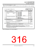
(4) A-D conversion frequency (φAD) select bit 0 (bit 7 at address 1E16), A-D conversion frequency
(φAD) select bit 1 (bit 4 at address 1F16
)
These bits are used to select the operation clock (φAD) of the A-D converter. Table 12.2.1 lists the
conversion time per one analog input pin.
Since the A-D converter’s comparator consists of capacity coupling amplifiers, be sure to keep that
Table 12.2.1 Conversion time per one analog input pin
Conversion time (µs) (Note)
A-D conversion
frequency (φAD)
select bit 1
A-D conversion
frequency (φAD)
select bit 0
fsys = 20 MHz
10-bit resolution
mode
φAD
Comparator
function
5.60
8-bit resolution
mode
0
0
1
1
0
1
0
1
f2 divided by 4
19.60
23.60
f2 divided by 2
9.80
11.80
2.80
f2
4.90
5.90
1.40
f1
2.45
Do not select.
0.70
Note: This applies when the peripheral devices’ clock select bits 0, 1 (bits 6, 7 at address BC16) = “00
AD ≥ 250 kHz while the A-D converter is active.
2
.”
φ
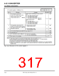
(5) A-D sweep pin select bits (bits 0 and 1 at address 1F16
)
These bits are used to select analog input pins in the single sweep mode, repeat sweep mode 0, or
repeat sweep mode 1. Pins which are not selected as analog input pins serve as programmable
I/O port pins or as I/O pins of other internal peripheral devices, which are multiplexed.
(6) Resolution select bit (bit 3 at address 1F16
)
This bit is used to select a resolution.
7905 Group User’s Manual Rev.1.0
12-8

 RENESAS [ RENESAS TECHNOLOGY CORP ]