A-D CONVERTER
12.2 Block description
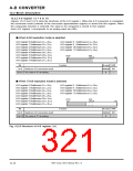
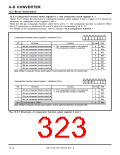
12.2.3 Comparator function select register 0, 1 and comparator result register 0, 1
Figure 12.2.7 shows the structures of comparator function select register 0 and 1; Figure 12.2.8 shows the
structures of comparator result register 0 and 1.
When the AN pin comparator function select bit is set to “1,” the comparator function is selected. When
i
the A-D conversion is performed, be sure to clear the corresponding bit to “0.”
For details of the comparator function, refer to section “12.6 Comparator function.”
b7 b6 b5 b4 b3 b2 b1 b0
Comparator function select register 0 (Address DC16
)
Bit
0
Bit name
Function
At reset R/W
0 : The comparator function is not selected.
1 : The comparator function is selected.
AN
AN
AN
AN
AN
AN
AN
AN
0
1
2
3
4
5
6
7
pin comparator function select bit
pin comparator function select bit
pin comparator function select bit
pin comparator function select bit
pin comparator function select bit
pin comparator function select bit
pin comparator function select bit
pin comparator function select bit
0
0
0
0
0
0
0
0
RW
RW
RW
RW
RW
RW
RW
RW
1
2
3
4
5
6
7
Note: Writing to comparator function select register 0 must be performed while the A-D converter halts.
b7 b6 b5 b4 b3 b2 b1 b0
Comparator function select register 1 (Address DD16
)
0 0
0
0
Bit
0
Bit name
Function
At reset R/W
0 : The comparator function is not selected.
1 : The comparator function is selected.
AN
AN
8
9
pin comparator function select bit
pin comparator function select bit
0
0
0
0
0
RW
RW
RW
RW
RW
1
2
AN10 pin comparator function select bit
AN11 pin comparator function select bit
3
7 to 4 Fix these bits to “0000.”
Note: Writing to comparator function select register 1 must be performed while the A-D converter halts.
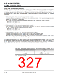
Fig. 12.2.7 Structures of comparator function select register 0 and 1
7905 Group User’s Manual Rev.1.0
12-12

 RENESAS [ RENESAS TECHNOLOGY CORP ]