TIMER A
7.4 Event counter mode
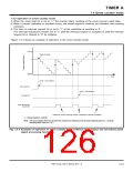
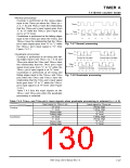
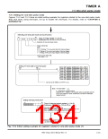
<Normal processing>
Countup is performed at the rising edges
input to the TAmIN pin when the TAmIN (m =
2, 3, 7, 8) and TAmOUT have the relationship
that the TAmIN pin’s input signal goes from
“L” to “H” while the TAmOUT pin’s input sig-
nal is at “H” level.
“H”
“L”
TAmOUT
“H”
“L”
TAmIN
(m = 2, 3, 7, 8)
Countup Countup
Countup Countdown Countdown Countdown
Countdown is performed at the falling edges
input to the TAmIN pin when the TAmIN and
TAmOUT have the relationship that the TAmIN
pin’s input signal goes from “H” to “L” while
the TAmOUT pin’s input signal is “H.” (See
Figure 7.4.7.)
+1
+1
+1
–1
–1
–1
Fig. 7.4.7 Normal processing
“H”
TAnOUT
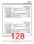
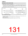
<Quadruple processing>
“L”
Countup is performed at all rising and fall-
ing edges input to the TAnOUT (n = 4, 9) and
TAnIN pins when the TAnIN and TAnOUT have
the relationship that the TAnIN pin’s input
signal level goes from “L” to “H” while the
TAnOUT pin’s input signal is at “H” level.
Countdown is performed at all rising and
falling edges input to the TAnOUT and TAnIN
pins when the TAnIN and TAnOUT have the
relationship that the TAnIN pin’s input signal
level goes from “H” to “L” while the TAnOUT
pin’s input signal is at “H” level. (See Figure
7.4.8.)
Counted up at all edges.
+1 +1 +1 +1 +1
Counted down at all edges.
–1 –1 –1
–1 –1
“H”
TAnIN
“L”
(n = 4, 9)
Counted up at all edges.
+1 +1 +1 +1 +1
Counted down at all edges.
–1 –1 –1
–1 –1
Fig. 7.4.8 Quadruple processing
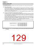
Table 7.4.3 lists the input signals on the
TAnOUT and TAnIN pins when the quadruple
processing is selected.
Table 7.4.3 TAnOUT and TAnIN pin’s input signals when quadruple processing is selected (n = 4, 9)
Input signal to TAnOUT pin
Input signal to TAnIN pin
Rising edge
Falling edge
“L” level
“H” level
“L” level
Rising edge
Falling edge
“H” level
“L” level
Rising edge
Falling edge
Countup
“H” level
Falling edge
Rising edge
“H” level
Countdown
“L” level
7905 Group User’s Manual Rev.1.0
7-27

 RENESAS [ RENESAS TECHNOLOGY CORP ]