TIMER A
7.4 Event counter mode
7.4.3 Switching between countup and countdown
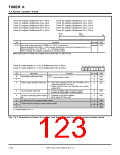
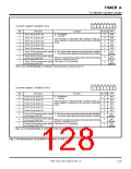
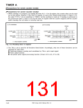
Figure 7.4.5 shows structures of the up-down registers 0 and 1.
The up-down register or the input signal from the TAiOUT pin is used to switch countup from and to
countdown. This switching is performed by the up-down bit when the up-down switching factor select bit
(bit 4 at addresses 5616 to 5A16, D616 to DA16) is “0,” and by the input signal from the TAiOUT pin when the
up-down switching factor select bit is “1.”
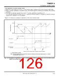
When the switching between countup and countdown is set while counting is in progress, this switching is
actually performed when the count source’s next valid edge is input.
(1) Switching by up-down bit
Countdown is performed when the up-down bit is “0,” and countup is performed when the up-down
bit is “1.” Figure 7.4.5 shows the structures of the up-down registers 0 and 1.
(2) Switching by TAiOUT pin’s input signal
Countdown is performed when the TAiOUT pin’s input signal is at “L” level, and countup is performed
when the TAiOUT pin’s input signal is at “H” level.
When using the TAiOUT pin’s input signal to switch countup from and to countdown, set the port P6,
port P2, and port P4 direction registers’ bits which correspond to the TAiOUT pin for the input mode.
7905 Group User’s Manual Rev.1.0
7-24

 RENESAS [ RENESAS TECHNOLOGY CORP ]