TIMER A
7.4 Event counter mode
7.4.1 Setting for event counter mode
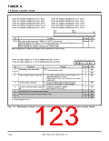
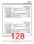
Figures 7.4.2 and 7.4.3 show an initial setting example for registers related to the event counter mode.
Note that when using interrupts, set up to enable the interrupts. For details, refer to “CHAPTER 6.
INTERRUPTS.”
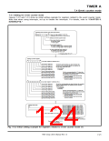
Selecting event counter mode and each function
b7
b0
Timer Ai mode register (i = 0 to 9)
(Addresses 5616 to 5A16, D616 to DA16)
0
1
ꢀ ꢀ
0
Selection of event counter mode
Pulse output function select bit
0: No pulse output
1: Pulse output
Count polarity select bit
0: Counts at falling edge of external signal.
1: Counts at rising edge of external signal.
Up-down switching factor select bit
0: Contents of up-down register
1: Input signal to TAiOUT pin
X: It may be either “0” or “1.”
Setting up–down register
b7
b0
Up–down register 0 (Address 4416
Timer A0 up–down bit
)
Set to the corresponding up–down bit when the
contents of the up-down register are selected as
the up-down switching factor.
Timer A1 up–down bit
Timer A2 up–down bit
Timer A3 up–down bit
Timer A4 up–down bit
0: Countdown
1: Countup
Timer A2 two–phase pulse
signal processing select bit
Timer A3 two–phase pulse
signal processing select bit
Set the corresponding bit to “1” when the
two–phase pulse signal processing function
is selected for timers A2 to A4.
0: Two–phase pulse signal processing
function disabled
Timer A4 two–phase pulse
signal processing select bit
1: Two–phase pulse signal processing
function enabled
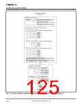
b7
b0
Up–down register 1 (Address C416
)
Set to the corresponding up–down bit when the contents
of the up-down register are selected as the up-down
switching factor.
0: Countdown
1: Countup
Timer A5 up–down bit
Timer A6 up–down bit
Timer A7 up–down bit
Timer A8 up–down bit
Timer A9 up–down bit
Set the corresponding bit to “1” when the
two–phase pulse signal processing function
is selected for timers A7 to A9.
0: Two–phase pulse signal processing
function disabled
Timer A7 two–phase pulse
signal processing select bit
Timer A8 two–phase pulse
signal processing select bit
1: Two–phase pulse signal processing
function enabled
Timer A9 two–phase pulse
signal processing select bit
Setting divide ratio
(b15)
b7
Timer A0 register (Addresses 4716, 4616
)
)
(b8)
b0 b7
Timer A1 register (Addresses 4916, 4816
b0
Timer A2 register (Addresses 4B16, 4A16
)
Timer A3 register (Addresses 4D16, 4C16
)
Timer A4 register (Addresses 4F16, 4E16
Timer A5 register (Addresses C716, C616
Timer A6 register (Addresses C916, C816
)
)
)
Timer A7 register (Addresses CB16, CA16
)
Timer A8 register (Addresses CD16, CC16
)
Can be set to“000016” to ”FFFF16” (n).
Timer A9 register (Addresses CF16, CE16
)
ꢀꢀThe counter divides the count source frequency by (n + 1)
when counting down, or by (FFFF16 – n + 1) when counting up.
Continued to Figure 7.4.3
on the next page
Fig. 7.4.2 Initial setting example for registers related to event counter mode (1)
7905 Group User’s Manual Rev.1.0
7-21

 RENESAS [ RENESAS TECHNOLOGY CORP ]