TIMER A
7.4 Event counter mode
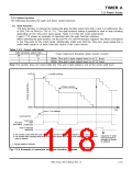
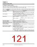
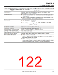
Table 7.4.2 Specifications of event counter mode (when using two-phase pulse signal processing
function in timers A2 to A4, A7 to A9)
Item
Specifications
Count source
External signal (two-phase pulse) input to the following pins:
TAjIN, TAjOUT (j = 2 to 4, 7 to 9)
Count operation
Division ratio
ꢀ Countup or countdown can be switched by external signal (two-
phase pulse).
ꢀ When a counter overflow or underflow occurs, reload register’s con-
tents are reloaded, and counting continues.
1
ꢀ For countdown
(n + 1)
n: Timer Aj register’s set value
ꢀ For countup
1
(FFFF16 – n + 1)
Count start condition
When the count start bit is set to “1.”
When the count start bit is cleared to “0.”
When a counter overflow or underflow occurs.
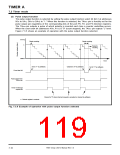
Two-phase pulse input
Count stop condition
Interrupt request occurrence timing
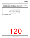
Function of the following pins:
TAjIN, TAjOUT (j = 2 to 4, 7 to 9)
Read from timer Aj register
Write to timer Aj register
Counter value can be read out by reading timer Aj register.
ꢀꢀWhile counting is stopped
When a value is written to timer Aj register, it is written to both of
the reload register and counter.
ꢀ While counting is in progress
When a value is written to timer Aj register, it is written only to the reload
register. (Transferred to the counter at the next reload timing.)
7905 Group User’s Manual Rev.1.0
7-19

 RENESAS [ RENESAS TECHNOLOGY CORP ]