TIMER A
7.4 Event counter mode
7.4 Event counter mode
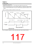
In this mode, the timer counts an external signal.
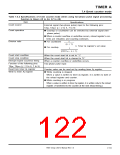
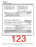
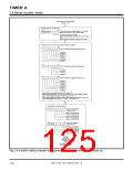
Tables 7.4.1 and 7.4.2 list the specifications of the event counter mode. Figure 7.4.1 shows the structures
of the timer Ai register and timer Ai mode register in the event counter mode.
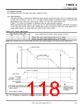
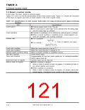
Table 7.4.1 Specifications of event counter mode (when not using two-phase pulse signal processing
function)
Item
Specifications
ꢀ External signal input to the TAiIN pin
Count source
ꢀ The count source’s valid edge can be selected from the falling edge
and the rising edge by software.
Count operation
Division ratio
ꢀ Countup or countdown can be switched by external signal or software.
ꢀ When a counter overflow or underflow occurs, reload register’s con-
tents are reloaded, and counting continues.
ꢀ For countdown
1
(n + 1)
n: Timer Ai register’s set value
ꢀ For countup
1
(FFFF16 – n + 1)
Count start condition
Count stop condition
Interrupt request occurrence timing
TAiIN pin’s function
When the count start bit is set to “1.”
When the count start bit is cleared to “0.”
When a counter overflow or underflow occurs.
Count source input
TAiOUT pin’s function
Programmable I/O port pin, pulse output pin, or countup/countdown
switch signal input pin
Read from timer Ai register
Write to timer Ai register
Counter value can be read out.
ꢀ While counting is stopped
When a value is written to timer Ai register, it is written to both of
the reload register and counter.
ꢀ While counting is in progress
When a value is written to timer Ai register, it is written only to the
reload register. (Transferred to the counter at the next reload timing.)
7905 Group User’s Manual Rev.1.0
7-18

 RENESAS [ RENESAS TECHNOLOGY CORP ]