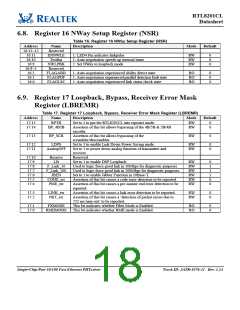
RTL8201CL
Datasheet
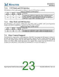
The RXDV signal will be asserted when decoded 5B are /J/K/ and will be de-asserted if the 5B are /T/R/
or IDLE in 100Mbps mode. In 10Mbps mode, the RXDV signal is the same as the CRS signal.
The RXER (Receive Error) signal will be asserted if any 5B decode errors occur such as invalid J/K,
invalid T/R, or invalid symbol. This pin will go high for one or more clock periods to indicate to the
reconciliation sublayer that an error was detected somewhere in the frame.
Note: The RTL8201CL does not use a TXER signal. This does not affect the transmit function.
7.1.2. Serial Management
The MAC layer device can use the MDC/MDIO management interface to control a maximum of 31
RTL8201CL devices, configured with different PHY addresses (00001b to 11111b). During a hardware
reset, the logic levels of pins 9, 10, 12, 13, 15 are latched into the RTL8201CL to be set as the PHY
address for management communication via the serial interface. Setting the PHY address to 00000b will
put the RTL8201CL into power down mode. The read and write frame structure for the management
interface is illustrated in Figure 3 and Figure 4.
MDC
Z
0
1
1
0
A4 A3 A2
A1 A0 R4 R3 R2 R1 R0
REGAD[4:0]
0
D14
D15 D13 D12
D11 D10 D9 D8 D7 D6 D5 D4 D3 D2 D1 D0
DATA
32 1s
MDIO
Preamble
ST
OP
PHYAD[4:0]
TA
Idle
MDIO is sourced by PHY. Clock data from PHY on rising edge of MDC
MDIO is sourced by MAC. Clock data into PHY on rising edge of MDC
Figure 3. Read Cycle
MDC
0
1
0
1
A4 A3 A2 A1 A0 R4 R3 R2 R1 R0
PHYAD[4:0] REGAD[4:0]
1
0
D14
D11 D10
D8 D7 D6 D5 D4 D3 D2
DATA
MDIO
D15
D13 D12
D9
D1 D0
32 1s
OP
Preamble
ST
TA
Idle
MDIO is sourced by MAC. Clock data into PHY on rising edge of MDC
Figure 4. Write Cycle
Table 21. Serial Management
Name
Description
Preamble
32 contiguous logical ‘1’s sent by the MAC on MDIO along with 32 corresponding cycles on MDC. This
provides synchronization for the PHY.
ST
OP
Start of Frame. Indicated by a 01 pattern.
Operation Code.
Read: 10
Write: 01
PHYAD
PHY Address. Up to 31 PHYs can be connected to one MAC. This 5-bit field selects which PHY the
frame is directed to.
REGAD
TA
Register Address. This is a 5-bit field that sets which of the 32 registers of the PHY this operation refers to.
Turnaround. This is a 2-bit time-spacing between the register address and the data field of a frame to
avoid contention during a read transaction. For a read transaction, both the STA and the PHY shall remain
in a high-impedance state for the first bit time of the turnaround. The PHY shall drive a zero bit during
the second bit time of the turnaround of a read transaction.
Data. These are the 16 bits of data.
DATA
IDLE
Idle Condition. Not truly part of the management frame. This is a high impedance state. Electrically, the
PHY’s pull-up resistor will pull the MDIO line to a logical ‘1’.
Single-Chip/Port 10/100 Fast Ethernet PHYceiver
15
Track ID: JATR-1076-21 Rev. 1.24

 REALTEK [ Realtek Semiconductor Corp. ]