MIL-M-38510/131A
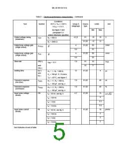
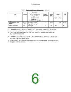
TABLE I. Electrical performance characteristics – Continued.
Conditions
-55°C ≤ T ≤ +125°C
Test
Symbol
Group A
subgroups
Device
type
Limits
Unit
A
±V
CC
= ±15 V,
see figure 3 and
paragraph 3.5
Min
Max
unless otherwise specified
f = 10 Hz – 10 kHz,
Broadband input noise
voltage
7
7
01,02
02
500
nV rms
dB
N
I(BB)
R
S
= 50 Ω, see fig. 7
Channel separation
CS
See fig. 8
80
1/ Tested at a) V
= 0 V, V
CC
= ±5 V, b) V
= ±12 V, V
CC
= ±15 V, c) V
CM
= 0 V, V = ±15 V.
CC
CM
CM
2/
V
= 0 to +10 for A
VS(+)
and V
OUT
= 0 to –10 for A
. R = 600 Ω for device type 01 and
VS(-)
OUT
R = 2 kΩ for device type 02.
L
L
3/ Tested at a) V
= ±5 V, V
OUT
= ±2 V, R = 600 Ω for device type 01, b) V
CC
= ±5 V, V = ±2 V,
OUT
CC
L
R = 2000 Ω for device types 01 and 02.
L
4/ Continuous short circuit limits are considerably less than the indicated test limits since maximum power
dissipation cannot be exceeded.
6

 RAYTHEON [ RAYTHEON COMPANY ]