MIL-M-38510/131A
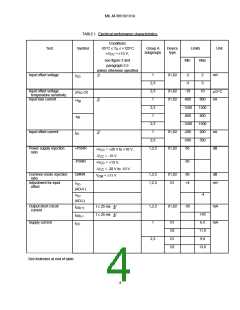
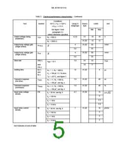
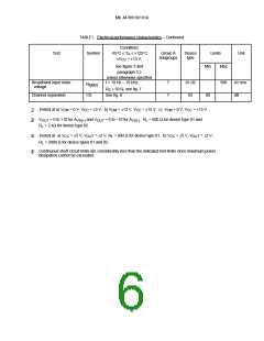
TABLE I. Electrical performance characteristics – Continued.
Conditions
-55°C ≤ T ≤ +125°C
Test
Symbol
Group A
subgroups
Device
type
Limits
Unit
A
±V
CC
= ±15 V,
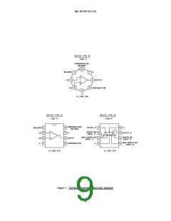
see figure 3 and
paragraph 3.5
Min
Max
unless otherwise specified
Output voltage swing
(maximum)
4,5,6
01
-10
-12
50
25
50
25
10
3
10
12
V
V
R = 600 Ω
L
OP
01,02
01,02
R = 2000 Ω
L
Output loop voltage gain
(single ended)
4
V/mV
V/mV
V/µs
2/
A
A
VS(±)
5,6
4
Output loop voltage gain
(single ended)
01,02
3/
VS
5,6
7,8
Slew rate
SR(+)
01
02
V
A
= 10 V
IN
and
SR(-)
ts(+)
and
Settling time
12
01,02
4
µs
= -1, R = 600 Ω,
V
L
C = 100 pF, 0.1 % error,
L
ts(-)
T = +25°C, see figure 5
A
Transient response
(rise time)
7,8
7,8
4,7
01,02
01,02
01,02
40
40
ns
%
T
A = +1, R = 600 Ω,
V L
R(tr)
C = 100 pF, see fig. 4
L
Transient response
(overshoot)
T
R(os)
A
V
= +1, R = 600 Ω,
L
C = 100 pF, see fig. 4
L
Input noise voltage
density
EN
15
9
f = 30 Hz, see fig. 6
o
nV/ Hz
f = 100 Hz
o
5.5
5.0
10
5
f = 1 kHz
o
f = 10 kHz
o
Input noise current
density
IN
7
01,02
pA/Hz
f = 30 Hz, see fig. 6
o
f = 100 Hz
o
2
f = 1 kHz
o
2
f = 10 kHz
o
See footnotes at end of table.
5

 RAYTHEON [ RAYTHEON COMPANY ]