VRS51L1050
The I2CNOACKIF bit is only set in master mode when
an acknowledge signal has not been detected after a
data transmission. The I2CNOACKIF flag must be
cleared manually.
I²C Address Register
The I2CADDR register contains the device address
that will be transmitted in master mode. The
MASTERRW bit of the I2CCTRL2 register holds the
value of address bit 0 (read/write operation) to be sent
by the master following the start condition.
The I2CRXACK bit is a read-only, active low flag that,
when cleared, indicates that an acknowledge signal
has been received from the master after an 8-bit data
transmission is completed in slave mode.
In slave mode, the content of the I2CADDR register is
compared with the incoming address sent by the I²C
bus master.
The RXACK bit will be set to 1 after a reset or when no
acknowledge signal is detected during the
acknowledge phase of slave data transmission. In this
case, the I²C interface will release the SDA line in
order to allow the bus master to generate a stop or
another start condition.
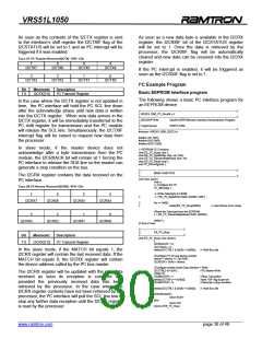
TABLE 36: I²C ADDRESS REGISTER (I2CADDR) - SFR –C1H
7
6
5
4
I2CADDR7
I2CADDR6
I2CADDR5
I2CADDR4
3
I2CADDR3
I2CADDR2
I2CADDR1
MSBCOMP
When the I2CMASTER is set to 1 by the processor, it
will force the I²C interface into master mode and
immediately initiate a transaction beginning with a start
and followed by the address stored in the I2CADDR (a
read or a write operation). In the case of a write
operation, the value present in the I2CTX register will
be sent to the bus, provided that a valid acknowledge
signal from the slave device is received after the
address transmission.
Bit
Mnemonic
Description
I2CADDR[7 :1]
7:1
I²C Address to be sent in master mode
I²C Slave address in slave mode
I²C Address compare
0: 7 address bits are compared in slave
mode
0
MSBCOMP
1: Compare only the four most significant
bits in slave mode
The MSBCOMP bit is used in slave mode. When this
bit is set to 1, the I²C interface will send an
acknowledge signal to the general call address (00h)
and a compare between the received address and the
value of the I2CADDR register will be made on the four
most significant bits.
When the I2CMASTER is cleared either by the
software or the I2CNACKIF flag, the I²C interface will
generate a stop on the I²C bus after the current byte
transmission is complete. Any data present in the
I2CTX register that was not transmitted will not be
transmitted.
When the MSBCOMP bit is cleared, the I²C interface
will only acknowledge to the calls that have an address
matching the upper seven bit of the I2CADDR register.
In the case where the I2CTXIF bit is set after a data
transmission fails, the I²C interface will immediately
release the SCL and SDA lines.
The I2CTXACK is the acknowledge status bit. The
value of I2CTXACK defines the value to be put in SDA
during the acknowledge phase of a slave data
reception. If I2CTXACK is set to 1, it indicates that no
acknowledge signal was sent to the master. If the
I2CTXACK bit is cleared, a valid acknowledge will be
sent to the master. This feature is useful for informing
the master device on the I²C bus that the VRS51L1050
is busy. The I2CTXACK is automatically cleared at
reset and can be set/cleared manually by the
processor.
I2CTX and I2CTX Registers
The I2CTX register contains the data to be transmitted
on the I²C interface.
In master mode, the content of the I2CTX register will
be sent to the interface’s shift register when the
receive acknowledge signal is received from the slave
device (I2CRXACK = 0).
In slave mode, the content of the I2CTX register will be
sent to the interface’s shift register when a matching
address is received (MATCH = 1) and bit 0 of the
incoming address is 1 (read operation).
______________________________________________________________________________________________
www.ramtron.com page 29 of 49

 RAMTRON [ RAMTRON INTERNATIONAL CORPORATION ]