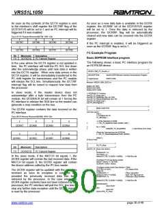
VRS51L1050
TABLE 34: I²C CONTROL REGISTER 2 (I2CCTRL2) - SFR –3H
The MASTERRW bit of the I2CCTRL2 register defines
the data direction in master mode. This bit serves as
bit 0 of the I²C address that will be sent to the I²C bus
in master mode.
7
6
5
-
4
-
MATCH
SLAVERW
3
2
1
0
RESTART
MASTERRW
To perform a read operation, the MASTERRW bit must
be set to 1. To perform a write operation, the
MASTERRW bit must be cleared.
Bit
Mnemonic
Description
7
MATCH
I²C Received address vs. I2CADDR match
indicator
0: No match between I²C address and
I2CADDR register content
1: Last I²C address received matches
value present in the I2CADDR register
Slave Mode Operation
0: Slave mode read (data received)
1: Slave mode write (data transmitted)
The I²C Status Register
The I2CSTATUS register provides most of the
indicators for the I²C interface. The four upper bits of
this register contain the interrupt flags and the lower
three bits are used for I²C interface control and
monitoring.
6
SLAVERW
5
4
3
-
-
TABLE 35: I²C STATUS REGISTER 1 (I2CSTATUS) – SFR C0H
RESTART
Master Mode Restart Signal
0: No action
7
6
5
4
1: The I²C interface will send a start
followed by I2CADDR content
I2CRXIF
I2CTXIF
I2CTXFAIL
I2CNOACKIF
2
1
0
-
-
3
2
1
0
I2CRXACK
I2CMASTER
I2CTXACK
MASTERRW Master Mode Data Direction
0: Master mode write
Bit
Mnemonic
I2CRXIF
I2CTXIF
I2CTXFAILIF
I2CNOACKIF
Description
I²C Reception Interrupt Flag
I²C Transmission Interrupt Flag
I²C Transmission Fail Interrupt Flag
I²C No Acknowledge Received interrupt
Flag
1: Master mode read
7
6
5
4
The MATCH bit of the I2CCTRL2 register is used for
slave I²C transactions. When the received data
following a start equals the value present in the
I2CADDR register, the MATCH bit will be set. In the
case where the MSBCOMP bit is set to 1, the MATCH
bit will be set when the upper four bits of the received
address correspond to the upper four bits in the
I2CADDR register. The processor can monitor the
MATCH bit to detect the beginning of an I²C
transaction addressed to it.
3
2
1
0
-
I2CRXACK
I2CMASTER
I2CTXACK
I²C Reception Acknowledge
I²C Master mode
I²C Transmission Acknowledge
The I2CRXIF flag will be set to 1 by the I²C upon the
reception of new data in the I2CRX register. Once the
data is loaded into the I2CRX register, the I2CRXIF
flag will be set. No new data received on the I²C
interface can be loaded into the I2CRX until the
processor retrieves the data already in the I2CRX
register. The I2CRXIF flag will be automatically cleared
when the processor reads the I2CRX. This bit can also
be cleared manually by the processor.
The SLAWERW bit is used in slave mode to inform the
processor of the data direction. This bit is updated after
the calling address is received in slave mode.
If data is going to be received, the SLAVERW bit will
be 0. If data is going to be transmitted, the SLAVERW
bit will be set to 1.
The I2CTXIF flag will be set to 1 by the I²C once the
data present in the I2CTX register is sent to the
interface’s shift register and the I2CTX register is ready
to receive the next data byte to be transmitted. The
I2CTXIF flag will be automatically cleared when new
data is written into the I2CTX register. It can also be
manually cleared by the processor.
The SLAVERW is especially useful in programs using
the interrupt to manage I²C slave transactions. The
SLAVERW bit is cleared upon device reset.
The RESETART is only active in master mode. When
this bit is set to 1, the I²C interface will generate a start
condition after the current acknowledge phase, and
then send the content of the I2CADDR register to the
I²C bus. If the addressed slave device fails to
acknowledge, the I2CTXFAIL bit of the I2CSTATUS
register will be set to 1, the RESTART bit will be
cleared and the I²C interface will release the bus. The
RESTART bit is automatically cleared after the I²C
interface has generated the start condition and after a
device reset.
The I2CTXFAILIF flag will be set to 1 if the data
transmission fails. The I2CTXFAILIF flag will also be
reset if an arbitration loss condition is detected by the
I²C interface in master mode. The arbitration loss
condition occurs when the master tries to transmit a 1
on the SDA line but it detects a 0 there. The
I2CTXFAILIF flag must be cleared manually.
______________________________________________________________________________________________
www.ramtron.com page 28 of 49

 RAMTRON [ RAMTRON INTERNATIONAL CORPORATION ]