VRS51L1050
I²C Control Registers
I²C-Compatible Interface
The primary I²C control registers are SFR registers,
I2CCTRL1 and I2CCTRL2, described below.
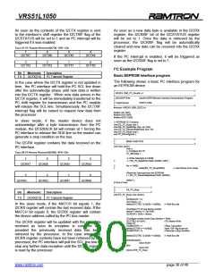
The VRS51L1050 provides an I²C-compatible interface
that operates in master and slave modes. In master
mode, the transaction speed is adjustable and can
reach speeds of up to 400kbps.
TABLE 32: I²C CONTROL REGISTER 1 (I2CCTRL1) – SFR C2H
7
6
-
5
-
4
-
The VRS51L1050’s I²C interface can simultaneously
accommodate a number of devices connected on the
same I²C bus, as long as the driving capacity load
does not exceed 400pF.
I2CEN
3
2
1
0
I2CBUSY
I2CCK[2:0]
A complete set of SFR registers control the I²C
interface. The I²C interface shares lines SCL and SDA
(respectively) of the P1.6 and P1.7 I/O ports. The I²C
controls these I/O lines when bits 6 and 7 of the
I2CPWME SFR registers are set to 1.
Bit
7
Mnemonic
I2CEN
Description
I²C Interface Enable
0 : I²C interface is disabled
1 : I²C Interface is enabled
6
5
4
3
-
-
-
TABLE 31: I2CPWME CONFIGURATION REGISTER (PWME) - SFR -9BH
I2CBUSY
I²C Bus Status
0: I²C bus is idle
7
6
5
-
4
-
1 I²C bus is busy
I²C Clock Speed Configuration
(see table below)
SDAE
SCLE
2
1
0
I2CCK2
I2CCK1
I2CCK0
3
2
1
0
PWM1E
PWM0E
In order for the I²C interface module to operate, it must
first be enabled by setting the I2CEN bit of the
I2CCTRL1 register to 1.
Bit
7
Mnemonic
SDAE
Description
I²C SDA Enable
0: P1.7 I/O operate as regular I/O
1: P1.7I/O is dedicated to I²C SDA
I²C SCL Enable
The BUSY bit indicates the current state of the I²C bus.
It is set to 1 when a start condition is detected on the
bus and is cleared when a stop condition is detected.
Before initiating a transaction on the I²C bus, make
sure the BUSY bit is cleared (I²C bus is free).
6
SCLE
0: P1.6 I/O operate as regular I/O
1: P1.6I/O is dedicated to I²C SCL
5
4
3
-
-
PWM1E
PWM1 Enable Register
0: PWM1 module is deactivated
1: PWM1 module is activated on P1.3
PWM1 Enable Register
0: PWM1 module is deactivated
1: PWM1 module is activated on P1.3
The I2CCKx bits of the I2CCTRL1 register define the
communication speed of the I²C interface when it
operates in master mode. By default, upon reset, the
I²C communication speed is set to Fosc/64.
2
PWM0E
1
0
-
-
TABLE 33: I²C CMMUNICATION SPEED IN MASTER MODE VX I2CCK[2:0]
I2CCK[2:0]
bit value
I²C
Com. speed
@Fosc
25MHz
Com. speed
@Fosc
communication.
speed
11.05
000
001
010
011
100
101
110
111
Fosc / 32
Fosc / 64 (default)
Fosc / 128
-s
346 kbps
173 kbps
84.4 kbps
43.2 kbps
21.6 kbps
10.8 kbps
5.4kbps
390 kbps
195 kbps
97.6 kbps
48.8 kbps
24.41 kbps
12.21 kbps
6.10 kbps
Fosc / 256
Fosc / 512
Fosc / 1024
Fosc / 2048
Fosc / 4096
2.7kbps
______________________________________________________________________________________________
www.ramtron.com page 27 of 49

 RAMTRON [ RAMTRON INTERNATIONAL CORPORATION ]