TOP252-262
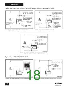
Typical Uses of MULTI-FUNCTION (M) Pin (cont.)
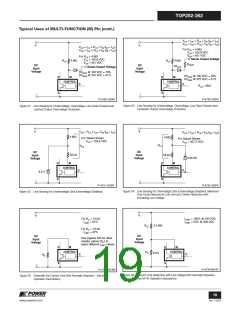
VUV = IUV × RLS + VM (IM = IUV
VOV = IOV × RLS + VM (IM = IOV
)
)
+
+
VUV = IUV × RLS + VM (IM = IUV
VOV = IOV × RLS + VM (IM = IOV
)
)
For RLS = 4 M7
VUV = 102.8 VDC
VOV = 451 VDC
For RLS = 4 M7
VUV = 102.8 VDC
VOV = 451 VDC
Sense Output Voltage
RLS
RLS
4 M7
4 M7
ROVP
DC
Input
DC
Input
VROVP
Sense Output Voltage
Voltage
Voltage
DCMAX @ 100 VDC = 76%
DCMAX @ 375 VDC = 41%
DCMAX @ 100 VDC = 76%
DCMAX @ 375 VDC = 41%
D
S
M
D
S
M
CONTROL
CONTROL
C
C
ROVP >3k7
-
-
PI-4729-120307
PI-4730-120307
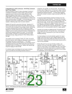
Figure 32. Line Sensing for Undervoltage, Overvoltage, Line Feed-Forward and
Hysteretic Output Overvoltage Protection.
Figure 31. Line Sensing for Undervoltage, Overvoltage, Line Feed-Forward and
Latched Output Overvoltage Protection.
+
+
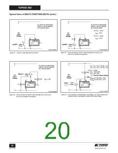
VUV = RLS × IUV + VM (IM = IUV
)
VOV = IOV × RLS + VM (IM = IOV
)
4 M7
4 M7
For Values Shown
For Values Shown
VUV = 103.8 VDC
VOV = 457.2 VDC
RLS
RLS
DC
Input
Voltage
DC
Input
Voltage
40 k7
55 k7
1N4148
D
S
M
D
S
M
CONTROL
CONTROL
C
C
6.2 V
-
-
PI-4732-120307
PI-4731-120307
Figure 34. Line Sensing for Overvoltage Only (Undervoltage Disabled). Maximum
Duty Cycle Reduced at Low Line and Further Reduction with
Increasing Line Voltage.
Figure 33. Line Sensing for Undervoltage Only (Overvoltage Disabled).
+
+
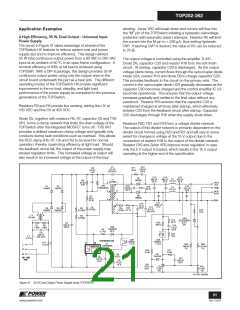
For RIL = 12 k7
ILIMIT = 61%
I
LIMIT = 100% @ 100 VDC
53% @ 300 VDC
ILIMIT
=
RLS
2.5 M7
For RIL = 19 k7
ILIMIT = 37%
DC
Input
Voltage
DC
Input
Voltage
See Figures 55b for other
resistor values (RIL) to
select different ILIMIT values.
D
S
M
D
S
M
CONTROL
CONTROL
RIL
6 k7
C
C
RIL
-
-
PI-4734-092107
PI-4733-021308
Figure 36. Current Limit Reduction with Line Voltage (Not Normally Required –
See M Pin Operation Description).
Figure 35. Externally Set Current Limit (Not Normally Required – See M Pin
Operation Description).
19
www.powerint.com
Rev. F 01/09

 POWERINT [ Power Integrations ]