TOP252-262
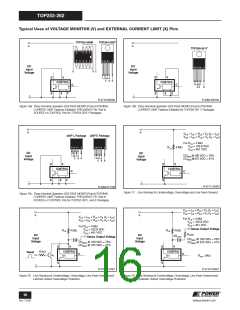
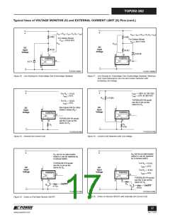
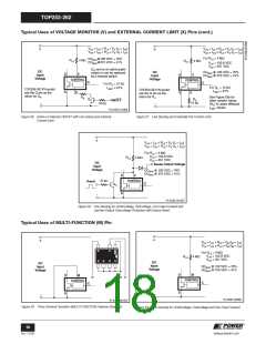
Typical Uses of VOLTAGE MONITOR (V) and EXTERNAL CURRENT LIMIT (X) Pins (cont.)
+
+
VUV = RLS × IUV + VV (IV = IUV
)
VOV = IOV × RLS + VV (IV = IOV
)
4 M7
40 k7
4 M7
For Values Shown
VUV = 103.8 VDC
For Values Shown
VOV = 457.2 VDC
RLS
R
LS
DC
Input
Voltage
DC
Input
Voltage
55 k7
1N4148
D
V
D
S
V
CONTROL
CONTROL
C
C
6.2 V
S
-
-
PI-4720-120307
PI-4721-120307
Figure 20. Line Sensing for Undervoltage Only (Overvoltage Disabled).
Figure 21. Line-Sensing for Overvoltage Only (Undervoltage Disabled). Maximum
Duty Cycle Reduced at Low Line and Further Reduction with
Increasing Line Voltage.
+
+
I
LIMIT = 100% @ 100 VDC
For RIL = 12 k7
53% @ 300 VDC
ILIMIT
=
ILIMIT = 61%
RLS
2.5 M7
TOP259-261YN would
use the G pin as the
return for RIL.
For RIL = 19 k7
ILIMIT = 37%
See Figure 55b for other
resistor values (RIL).
DC
Input
Voltage
DC
Input
Voltage
D
S
D
S
CONTROL
X
CONTROL
C
C
TOP259-261YN would
use the G pin as the
return for RIL.
X
RIL
RIL
6 k7
-
-
PI-4723-011008
PI-4722-021308
Figure 22. External Set Current Limit.
Figure 23. Current Limit Reduction with Line Voltage.
+
+
Q
R can be an optocoupler
QR can be an optocoupler
output or can be replaced by
a manual switch.
output or can be replaced
by a manual switch.
TOP259-261YN would
use the G pin as the
return for QR.
For RIL =12 k7
I
LIMIT = 61%
For RIL = 19 k7
LIMIT = 37%
DC
Input
Voltage
DC
Input
Voltage
D
D
S
CONTROL
CONTROL
I
C
C
TOP259-261YN would
use the G pin as the
return for QR.
S
X
X
RIL
ON/OFF
QR
QR
ON/OFF
47 K7
-
16 k7
-
PI-2625-011008
PI-4724-011008
Figure 25. Active-on Remote ON/OFF with Externally Set Current Limit.
Figure 24. Active-on (Fail Safe) Remote ON/OFF.
17
www.powerint.com
Rev. F 01/09

 POWERINT [ Power Integrations ]