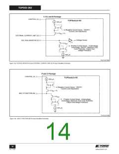
TOP252-262
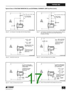
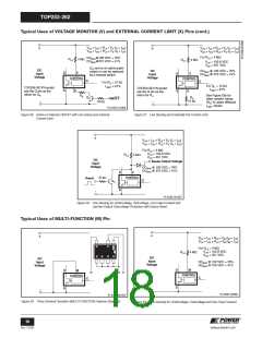
Typical Uses of VOLTAGE MONITOR (V) and EXTERNAL CURRENT LIMIT (X) Pins (cont.)
VUV = IUV × RLS + VV (IV = IUV
)
VUV = IUV x RLS + VV (IV = IUV
)
+
+
VOV = IOV × RLS + VV (IV = IoV
)
VOV = IOV x RLS + VV (IV = IoV
)
For RLS = 4 M7
DCMAX@100 VDC = 76%
DCMAX@375 VDC = 41%
4 M7
RLS
4 M7
RLS
VUV = 102.8 VDC
VOV = 451 VDC
QR can be an optocoupler
DC
Input
Voltage
DC
Input
Voltage
DCMAX @ 100 VDC = 76%
DCMAX @ 375 VDC = 41%
output or can be replaced
by a manual switch.
D
S
V
D
S
V
CONTROL
CONTROL
C
C
For RIL =12 k7
For RIL = 12 k7
ILIMIT = 61%
ILIMIT = 61%
TOP259-261YN would
use the G pin as the
return for QR.
TOP259-261YN would
use the G pin as the
return for RIL.
X
X
See Figure 55b for
other resistor values
(RIL) to select different
ILIMIT values.
RIL
QR
RIL
12 k7
ON/OFF
16 k7
-
-
PI-4725-011008
Figure 26. Active-on Remote ON/OFF with Line-Sense and External
Current Limit.
Figure 27. Line Sensing and Externally Set Current Limit.
+
VUV = IUV × RLS + VV (IV = IUV
)
VOV = IOV × RLS + VV (IV = IOV
)
For RLS = 4 M7
VUV = 102.8 VDC
VOV = 451 VDC
RLS
4 M7
DC
Input
Sense Output Voltage
Voltage
DCMAX @ 100 VDC = 76%
DCMAX @ 375 VDC = 41%
D
S
V
10 k7
CONTROL
Reset
C
QR
-
PI-4756-121007
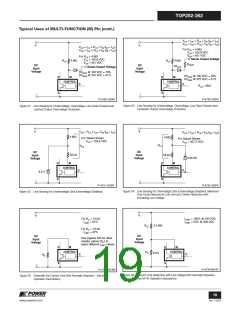
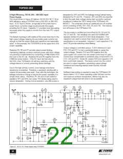
Figure 28. Line-Sensing for Undervoltage, Overvoltage, Line Feed-Forward and
Latched Output Overvoltage Protection with Device Reset.
Typical Uses of MULTI-FUNCTION (M) Pin
+
+
VUV = IUV × RLS + VM (IM = IUV
)
VOV = IOV × RLS + VM (IM = IOV
)
D
S
C
S
For RLS = 4 M7
VUV = 102.8 VDC
VOV = 451 VDC
M
S
RLS
4 M7
S
DC
Input
Voltage
DC
Input
Voltage
DCMAX @ 100 VDC = 76%
DCMAX @ 375 VDC = 41%
D
S
M
D
S
M
D
S
C
CONTROL
CONTROL
C
C
-
-
PI-4728-120307
PI-4727-061207
Figure 29. Three Terminal Operation (MULTI-FUNCTION Features Disabled).
Figure 30. Line Sensing for Undervoltage, Overvoltage and Line Feed-Forward.
18
Rev. F 01/09
www.powerint.com

 POWERINT [ Power Integrations ]