TOP242-249
DCMAX at higher line voltages helps prevent transformer
saturation due to large load transients in forward converter
applications. DCMAX of 38% at the OV threshold was chosen to
ensure that the power capability of the TOPSwitch-GX is not
restricted by this feature under normal operation.
open). When the TOPSwitch-GX is remotely turned on after
entering this mode, it will initiate a normal start-up sequence
with soft-start the next time the CONTROL pin reaches 5.8 V.
In the worst case, the delay from remote on to start-up can be
equal to the full discharge/charge cycle time of the CONTROL
pin, which is approximately 125 ms for a 47 µF CONTROL pin
capacitor. This reduced consumption remote off mode can
eliminateexpensiveandunreliablein-linemechanicalswitches.
It also allows for microprocessor controlled turn-on and turn-
off sequences that may be required in certain applications such
as inkjet and laser printers.
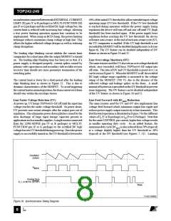
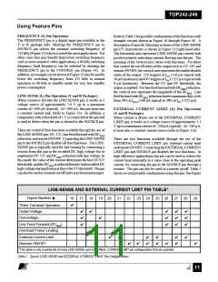
Remote ON/OFF and Synchronization
TOPSwitch-GX can be turned on or off by controlling the
current into the LINE-SENSE pin or out from the EXTERNAL
CURRENT LIMIT pin (Y or R package) and into or out from
the MULTI-FUNCTION pin (P or G package) (see Figure 11).
Inaddition,theLINE-SENSEpinhasa1Vthresholdcomparator
connected at its input. This voltage threshold can also be used
to perform remote ON/OFF control. This allows easy
implementation of remote ON/OFF control of TOPSwitch-GX
in several different ways. A transistor or an optocoupler output
connected between the EXTERNAL CURRENT LIMIT or
LINE-SENSEpins(YorRpackage)ortheMULTI-FUNCTION
pin (P or G package) and the SOURCE pin implements this
function with “active-on” (Figure 22, 29 and 36) while a
transistor or an optocoupler output connected between the
LINE-SENSEpin(YorRpackage)ortheMULTI-FUNCTION
(P or G package) pin and the CONTROL pin implements the
function with “active-off” (Figure 23 and 37).
Soft-Start
Two on-chip soft-start functions are activated at start-up with a
duration of 10 ms (typical). Maximum duty cycle starts from
0% and linearly increases to the default maximum of 78% at the
end of the 10 ms duration and the current limit starts from about
85% and linearly increases to 100% at the end of the 10ms
duration. In addition to start-up, soft-start is also activated at
each restart attempt during auto-restart and when restarting
after being in hysteretic regulation of CONTROL pin voltage
(VC), due to remote off or thermal shutdown conditions. This
effectivelyminimizescurrentandvoltagestressesontheoutput
MOSFET,theclampcircuitandtheoutputrectifierduringstart-
up. This feature also helps minimize output overshoot and
prevents saturation of the transformer during start-up.
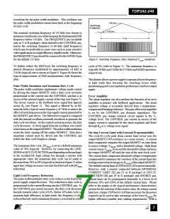
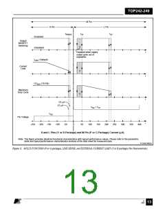
When a signal is received at the LINE-SENSE pin or the
EXTERNAL CURRENT LIMIT pin (Y or R package) or the
MULTI-FUNCTIONpin(PorGpackage)todisabletheoutput
through any of the pin functions such as OV, UV and remote
ON/OFF,TOPSwitch-GXalwayscompletesitscurrentswitching
cycle, as illustrated in Figure 10, before the output is forced off.
The internal oscillator is stopped slightly before the end of the
current cycle and stays there as long as the disable signal exists.
When the signal at the above pins changes state from disable to
enable, the internal oscillator starts the next switching cycle.
This approach allows the use of this pin to synchronize
TOPSwitch-GX to any external signal with a frequency lower
than its internal switching frequency.
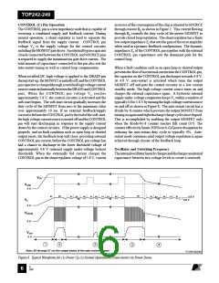
Shutdown/Auto-Restart
To minimize TOPSwitch-GX power dissipation under fault
conditions, the shutdown/auto-restart circuit turns the power
supply on and off at an auto-restart duty cycle of typically 4%
if an out of regulation condition persists. Loss of regulation
interrupts the external current into the CONTROL pin. VC
regulation changes from shunt mode to the hysteretic auto-
restart mode as described in CONTROL pin operation section.
When the fault condition is removed, the power supply output
becomes regulated, VC regulation returns to shunt mode, and
normal operation of the power supply resumes.
As seen above, the remote ON/OFF feature allows the
TOPSwitch-GX to be turned on and off instantly, on a cycle-by-
cycle basis, with very little delay. However, remote ON/OFF
can also be used as a standby or power switch to turn off the
TOPSwitch-GX and keep it in a very low power consumption
state for indefinitely long periods. If the TOPSwitch-GXis held
inremoteoffstateforlongenoughtimetoallowtheCONTROL
pin to dishcharge to the internal supply under-voltage threshold
of 4.8 V (approximately 32 ms for a 47 µF CONTROL pin
capacitance), the CONTROL pin goes into the hysteretic mode
of regulation. In this mode, the CONTROL pin goes through
alternate charge and discharge cycles between 4.8 V and 5.8 V
(see CONTROL pin operation section above) and runs entirely
off the high voltage DC input, but with very low power
consumption (160 mW typical at 230 VAC with M or X pins
Hysteretic Over-Temperature Protection
Temperature protection is provided by a precision analog
circuit that turns the output MOSFET off when the junction
temperature exceeds the thermal shutdown temperature
(140°Ctypical). Whenthejunctiontemperaturecoolstobelow
thehysteretictemperature,normaloperationresumesproviding
automatic recovery. A large hysteresis of 70 °C (typical) is
provided to prevent overheating of the PC board due to a
continuous fault condition. VC is regulated in hysteretic mode
and a 4.8 V to 5.8 V (typical) sawtooth waveform is present on
the CONTROL pin while in thermal shutdown.
Bandgap Reference
All critical TOPSwitch-GX internal voltages are derived from a
temperature-compensatedbandgapreference. Thisreferenceis
E
7/01
August 8, 2000
9

 POWERINT [ Power Integrations ]