TOP242-249
Using Feature Pins
FREQUENCY (F) Pin Operation
RefertoTable2forpossiblecombinationsofthefunctionswith
example circuits shown in Figure 16 through Figure 40. A
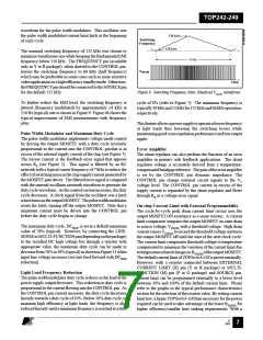
description of specific functions in terms of the LINE-SENSE
pin I/V characteristic is shown in Figure 11 (right hand side).
The horizontal axis represents LINE-SENSE pin current with
positive polarity indicating currents flowing into the pin. The
meaning of the vertical axes varies with functions. For those
that control the on/off states of the output such as UV, OV and
remote ON/OFF, the vertical axis represents the enable/disable
states of the output. UV triggers at IUV (+50 µA typical with
30 µA hysteresis) and OV triggers at IOV (+225 µA typical with
8 µA hysteresis). Between the UV and OV thresholds, the
output is enabled. For line feed forward with DCMAX reduction,
the vertical axis represents the magnitude of the DCMAX. Line
feed forward with DC reduction lowers maximum duty cycle
from 78% at IL(DC) (+6M0AµXA typical) to 38% at IOV (+225 µA).
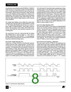
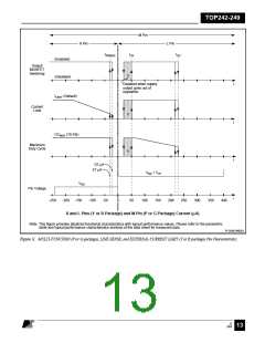
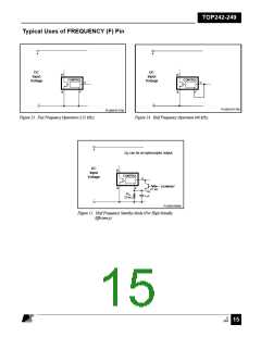
The FREQUENCY pin is a digital input pin available in the
Y or R package only. Shorting the FREQUENCY pin to
SOURCE pin selects the nominal switching frequency of
132 kHz (Figure 13) which is suited for most applications. For
other cases that may benefit from lower switching frequency
such as noise sensitive video applications, a 66 kHz switching
frequency (half frequency) can be selected by shorting the
FREQUENCY pin to the CONTROL pin (Figure 14). In
addition, an example circuit shown in Figure 15 may be used to
lower the switching frequency from 132 kHz in normal
operation to 66 kHz in standby mode for very low standby
power consumption.
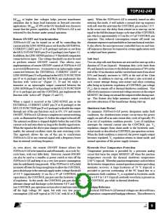
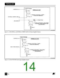
LINE-SENSE (L) Pin Operation (Y and R Packages)
When current is fed into the LINE-SENSE pin, it works as a
voltage source of approximately 2.6 V up to a maximum
current of +400 µA (typical). At +400 µA, this pin turns into
a constant current sink. Refer to Figure 12a. In addition, a
comparator with a threshold of 1 V is connected at the pin and
is used to detect when the pin is shorted to the SOURCE pin.
EXTERNAL CURRENT LIMIT (X) Pin Operation
(Y and R Packages)
When current is drawn out of the EXTERNAL CURRENT
LIMIT pin, it works as a voltage source of approximately 1.3
V up to a maximum current of –240 µA (typical). At –240 µA,
it turns into a constant current source (refer to Figure 12a).
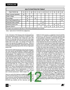
There are a total of four functions available through the use of
the LINE-SENSE pin: OV, UV, line feed forward with DCMAX
reduction,andremoteON/OFF. ConnectingtheLINE-SENSE
pin to the SOURCE pin disables all four functions. The LINE-
SENSE pin is typically used for line sensing by connecting a
resistor from this pin to the rectified DC high voltage bus to
implement OV, UV and DCMAX reduction with line voltage. In
this mode, the value of the resistor determines the line OV/UV
thresholds, andtheDCMAX isreducedlinearlywithrectifiedDC
highvoltagestartingfromjustabovetheUVthreshold. Thepin
canalsobeusedasaremoteon/offandasynchronizationinput.
There are two functions available through the use of the
EXTERNAL CURRENT LIMIT pin: external current limit
andremoteON/OFF. ConnectingtheEXTERNALCURRENT
LIMIT pin and SOURCE pin disables the two functions. In
high efficiency applications this pin can be used to reduce the
current limit externally to a value close to the operating peak
current, by connecting the pin to the SOURCE pin through a
resistor. The pin can also be used as a remote on/off. Table 2
shows several possible combinations using this pin. See Figure
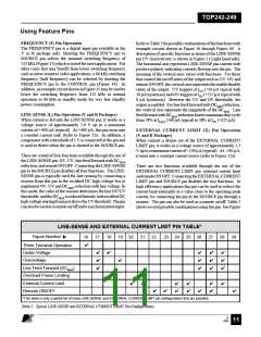
LINE-SENSE AND EXTERNAL CURRENT LIMIT PIN TABLE*
Figure Number
16
17
18
19 20
21
22
23 24
25 26
27
28
29
✔
Three Terminal Operation
Under-Voltage
✔
✔
✔
✔
✔
✔
✔
✔
✔
✔
✔
✔
✔
Overvoltage
✔
Line Feed Forward (DCMAX
Overload Power Limiting
External Current Limit
Remote ON/OFF
)
✔
✔
✔
✔
✔
✔
✔
✔
✔
✔
✔
✔
✔
✔
*This table is only a partial list of many LINE-SENSE and EXTERNAL CURRENT LIMIT pin configurations that are possible.
Table 2. Typical LINE-SENSE and EXTERNAL CURRENT LIMIT Pin Configurations.
E
7/01
August 8, 2000
11

 POWERINT [ Power Integrations ]