TOP242-249
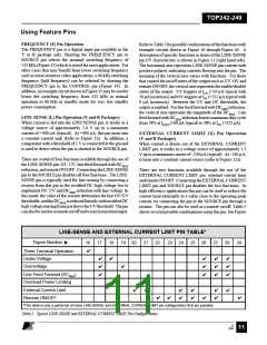
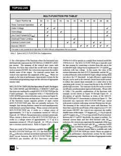
MULTI-FUNCTION PIN TABLE*
Figure Number
30
31
32
33
34
35
36
37
38
39
40
✔
Three Terminal Operation
Under-Voltage
✔
✔
✔
✔
✔
✔
✔
Overvoltage
✔
Line Feed Forward (DCMAX
Overload Power Limiting
External Current Limit
Remote ON/OFF
)
✔
✔
✔
✔
✔
✔
✔
✔
✔
✔
*This table is only a partial list of many MULTI-FUNCTION pin configurations that are possible.
Table 3. Typical MULTI-FUNCTION Pin Configurations.
11 for a description of the functions where the horizontal axis
(left hand side) represents the EXTERNAL CURRENT LIMIT
pin current. The meaning of the vertical axes varies with
function. For those that control the on/off states of the output
such as remote ON/OFF, the vertical axis represents the enable/
disable states of the output. For external current limit, the
vertical axis represents the magnitude of the ILIMIT. Please see
graphs in the typical performance characteristics section for the
current limit programming range and the selection of appropriate
resistor value.
TOPSwitch-GX to operate in a simple three terminal mode like
TOPSwitch-II. The MULTI-FUNCTION pin is typically used
for line sensing by connecting a resistor from this pin to the
rectifiedDChighvoltagebustoimplementOV, UVandDCMAX
reduction with line voltage. In this mode, the value of the
resistor determines the line OV/UV thresholds, and the DCMAX
is reduced linearly with rectified DC high voltage starting from
just above the UV threshold. In high efficiency applications
this pin can be used in the external current limit mode instead,
to reduce the current limit externally to a value close to the
operating peak current, by connecting the pin to the SOURCE
pinthrougharesistor. Thesamepincanalsobeusedasaremote
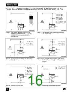
on/off and a synchronization input in both modes. Please refer
to Table 3 for possible combinations of the functions with
example circuits shown in Figure 30 through Figure 40. A
description of specific functions in terms of the MULTI-
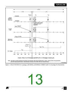
FUNCTION pin I/V characteristic is shown in Figure 11. The
horizontal axis represents MULTI-FUNCTION pin current
with positive polarity indicating currents flowing into the pin.
The meaning of the vertical axes varies with functions. For
those that control the on/off states of the output such as UV, OV
and remote ON/OFF, the vertical axis represents the enable/
disable states of the output. UV triggers at IUV (+50 µA typical)
and OV triggers at IOV (+225 µA typical with 30 µA hysteresis).
Between the UV and OV thresholds, the output is enabled. For
external current limit and line feed forward with DCMAX
reduction, the vertical axis represents the magnitude of the ILIMIT
and DCMAX. Line feed forward with DCMAX reduction lowers
maximum duty cycle from 78% at IM(DC) (+60 µA typical) to 38%
at IOV (+225 µA). External current limit is available only with
negative MULTI-FUNCTION pin current. Please see graphs in
the typical performance characteristics section for the current
limit programming range and the selection of appropriate resistor
value.
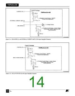
MULTI-FUNCTION(M)PinOperation(PandGPackages)
The LINE-SENSE and EXTERNAL CURRENT LIMIT pin
functionsarecombinedtoasingleMULTI-FUNCTIONpinfor
P and G packages. The comparator with a 1 V threshold at the
LINE-SENSEpinisremovedinthiscaseasshowninFigure2b.
All of the other functions are kept intact. However, since some
of the functions require opposite polarity of input current
(MULTI-FUNCTION pin), they are mutually exclusive. For
example, line sensing features cannot be used simultaneously
with external current limit setting. When current is fed into the
MULTI-FUNCTION pin, it works as a voltage source of
approximately 2.6 V up to a maximum current of +400 µA
(typical). At+400µA,thispinturnsintoaconstantcurrentsink.
When current is drawn out of the MULTI-FUNCTION pin, it
works as a voltage source of approximately 1.3 V up to a
maximum current of –240 µA (typical). At –240 µA, it turns
into a constant current source. Refer to Figure 12b.
There are a total of five functions available through the use of
the MULTI-FUNCTION pin: OV, UV, line feed forward with
DCMAX reduction,externalcurrentlimitandremoteON/OFF. A
short circuit between the MULTI-FUNCTION pin and
SOURCE pin disables all five functions and forces
E
7/01
August 8, 2000
12

 POWERINT [ Power Integrations ]