TOP242-250
Parameter
Conditions
SOURCE = 0 V; TJ = -40 to 125 °C
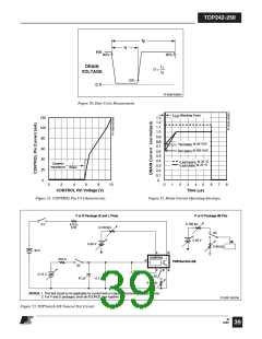
See Figure 53
Symbol
Min
Typ
Max
Units
(Unless Otherwise Specified)
MULTI-FUNCTION, LINSE-SENSE AND EXTERNAL CURRENT LIMIT INPUTS (cont.)
X, L or M Pin
0.6
1.0
2.5
1.0
Remote OFF
DRAIN Supply
Current
See Figure 71
VDRAIN = 150 V
TJ = 25 °C
Floating
ID(RMT)
mA
L or M Pin Shorted
to CONTROL
1.6
From Remote ON to Drain Turn-On
See Note B
tR(ON)
µs
µs
Remote ON Delay
Remote OFF
Setup Time
Minimum Time Before Drain Turn-On
to Disable Cycle, See Note B
tR(OFF)
2.5
FREQUENCY INPUT
FREQUENCY Pin
Threshold Voltage
VF
IF
See Note B
VF = VC
2.9
40
V
FREQUENCY Pin
Input Current
10
100
µA
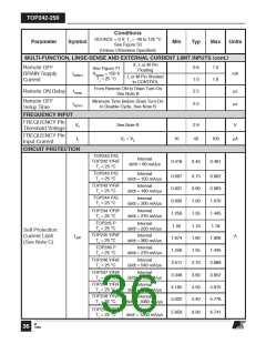
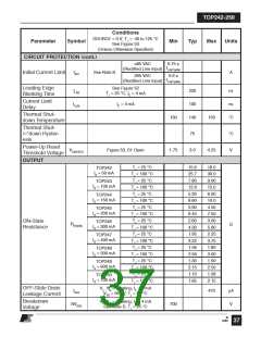
CIRCUIT PROTECTION
TOP242 P/G
TOP242 Y/R/F
TJ = 25 °C
Internal
di/dt = 90 mA/µs
0.418
0.45
0.481
TOP243 P/G
TJ = 25 °C
Internal
di/dt = 150 mA/µs
0.697
0.837
0.930
1.256
1.02
0.75
0.90
1.00
1.35
1.10
1.80
1.35
2.70
3.60
4.50
5.40
0.802
0.963
1.070
1.445
1.18
TOP243 Y/R/F
TJ = 25 °C
Internal
di/dt = 180 mA/µs
TOP244 P/G
TJ = 25 °C
Internal
di/dt = 200 mA/µs
TOP244 Y/R/F
TJ = 25 °C
Internal
di/dt = 270 mA/µs
TOP245 P
TJ = 25 °C
Internal
di/dt = 220 mA/µs
Self Protection
TOP245 Y/R/F
TJ = 25 °C
Internal
di/dt = 360 mA/µs
ILIMIT
A
Current Limit
(See Note C)
1.674
1.256
2.511
3.348
4.185
5.022
1.926
1.445
2.889
3.852
4.815
5.778
TOP246 P
TJ = 25 °C
Internal
di/dt = 270 mA/µs
TOP246 Y/R/F
TJ = 25 °C
Internal
di/dt = 540 mA/µs
TOP247 Y/R/F
TJ = 25 °C
Internal
di/dt = 720 mA/µs
TOP248 Y/R/F
TJ = 25 °C
Internal
di/dt = 900 mA/µs
TOP249 Y/R/F
TJ = 25 °C
Internal
di/dt = 1080 mA/µs
TOP250 Y/R/F
TJ = 25 °C
Internal
di/dt = 1260 mA/µs
5.859
6.30
6.741
M
36 12/04

 POWERINT [ Power Integrations ]