TOP242-250
Conditions
SOURCE = 0 V; TJ = -40 to 125 °C
See Figure 53
Parameter
Symbol
Min
Typ
Max
Units
(Unless Otherwise Specified)
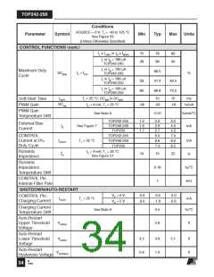
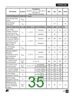
SHUTDOWN/AUTO-RESTART (cont.)
Auto-Restart Duty
DC(AR)
Cycle
4
8
%
Auto-Restart
f(AR)
Frequency
1.0
Hz
MULTI-FUNCTION (M), LINE-SENSE (L) AND EXTERNAL CURRENT LIMIT (X) INPUTS
Line Under-
Threshold
Hysteresis
44
50
30
54
µA
µA
Voltage Threshold
Current and Hys-
teresis (M or L Pin)
IUV
TJ = 25 °C
Line Overvoltage
or Remote ON/OFF
Threshold Current
and Hysteresis
(M or L Pin)
Threshold
Hysteresis
210
225
8
240
µA
µA
V
IOV
TJ = 25 °C
L Pin Voltage
Threshold
VL(TH)
0.5
-35
1.0
-27
5
1.6
-20
Remote ON/OFF
Negative
Threshold Current
and Hysteresis
(M or X Pin)
Threshold
Hysteresis
µA
IREM (N)
TJ = 25 °C
µA
µA
µA
V
L or M Pin Short
Circuit Current
IL(SC) or
IM(SC)
VL, VM = VC
300
400
520
Normal Mode
Auto-Restart Mode
IL or IM = 50 µA
IL or IM = 225 µA
IX = -50 µA
-300
-110
1.90
2.30
1.26
1.18
1.24
1.13
-240
-90
-180
-70
X or M Pin Short
Circuit Current
IX(SC) or
IM(SC)
VX, VM = 0 V
2.50
2.90
1.33
1.24
1.31
1.19
3.00
3.30
1.40
1.30
1.39
1.25
L or M Pin Voltage
(Positive Current)
VL, VM
X Pin Voltage
(Negative Current)
VX
V
IX = -150 µA
IM = -50 µA
M Pin Voltage
(Negative Current)
VM
V
IM = -150 µA
Maximum Duty
Cycle Reduction
Onset Threshold
Current
IL(DC) or
IM(DC)
TJ = 25 °C
40
60
75
µA
M
12/04
35

 POWERINT [ Power Integrations ]