RELEASED
PM7350 S/UNI DUPLEX
DATA SHEET
PMC-1980581
ISSUE 8
DUAL SERIAL LINK PHY MULTIPLEXER
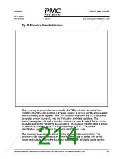
Fig. 16 Boundary Scan Architecture
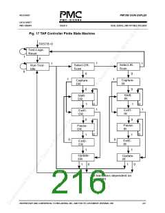
The boundary scan architecture consists of a TAP controller, an instruction
register with instruction decode, a bypass register, a device identification register
and a boundary scan register. The TAP controller interprets the TMS input and
generates control signals to load the instruction and data registers. The
instruction register with instruction decode block is used to select the test to be
executed and/or the register to be accessed. The bypass register offers a single-
bit delay from primary input, TDI to primary output, TDO. The device
identification register contains the device identification code.
The boundary scan register allows testing of board inter-connectivity. The
boundary scan register consists of a shift register place in series with device
inputs and outputs. Using the boundary scan register, all digital inputs can be
PROPRIETARY AND CONFIDENTIAL TO PMC-SIERRA, INC., AND FOR ITS CUSTOMERS’ INTERNAL USE
199

 PMC [ PMC-SIERRA, INC ]