RELEASED
PM7350 S/UNI DUPLEX
DATA SHEET
PMC-1980581
ISSUE 8
DUAL SERIAL LINK PHY MULTIPLEXER
Update-IR
The update instruction register state is used to load a new instruction into the
instruction register. The new instruction must be scanned in using the Shift-IR
state. The load occurs on the falling edge of TCK.
The Pause-DR and Pause-IR states are provided to allow shifting through the
test data and/or instruction registers to be momentarily paused.
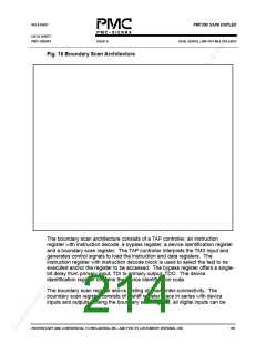
12.5.1 Boundary Scan Instructions
The following is an description of the standard instructions. Each instruction
selects an serial test data register path between input, TDI and output, TDO.
BYPASS
The bypass instruction shifts data from input, TDI to output, TDO with one TCK
clock period delay. The instruction is used to bypass the device.
EXTEST
The external test instruction allows testing of the interconnection to other
devices. When the current instruction is the EXTEST instruction, the boundary
scan register is place between input, TDI and output, TDO. Primary device
inputs can be sampled by loading the boundary scan register using the
Capture-DR state. The sampled values can then be viewed by shifting the
boundary scan register using the Shift-DR state. Primary device outputs can be
controlled by loading patterns shifted in through input TDI into the boundary scan
register using the Update-DR state.
SAMPLE
The sample instruction samples all the device inputs and outputs. For this
instruction, the boundary scan register is placed between TDI and TDO. Primary
device inputs and outputs can be sampled by loading the boundary scan register
using the Capture-DR state. The sampled values can then be viewed by shifting
the boundary scan register using the Shift-DR state.
IDCODE
The identification instruction is used to connect the identification register between
TDI and TDO. The device's identification code can then be shifted out using the
Shift-DR state.
PROPRIETARY AND CONFIDENTIAL TO PMC-SIERRA, INC., AND FOR ITS CUSTOMERS’ INTERNAL USE
203

 PMC [ PMC-SIERRA, INC ]