S/UNI®-ATLAS-3200 Telecom Standard Product Data Sheet
Preliminary
11.2 Core Registers
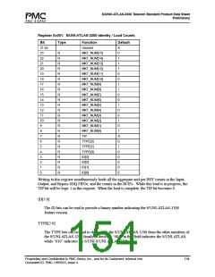
Register 0x000: S/UNI-ATLAS-3200 Master Configuration And Reset
Bit
31:18
17
16
15
14
13
12
11
10
9
8
7
6
5
4
3
2
1
Type
Function
Unused
Reserved
Reserved
FREE[7]
FREE[6]
FREE[5]
FREE[4]
FREE[3]
Default
X
0
0
0
0
0
0
0
0
0
0
1
0
0
0
0
0
1
1
R/W
R/W
R/W
R/W
R/W
R/W
R/W
R/W
R/W
R/W
R/W
R/W
R/W
R/W
R/W
R/W
R/W
R/W
FREE[2]
FREE[1]
FREE[0]
POS_UL3B
Egress_IngressB
DRAM_BUSY_EN
SRAM_BUSY_EN
BUSYPOL
Reserved
STANDBY
RESET
0
RESET
The RESET bit allows the S/UNI-ATLAS-3200 to be reset under software control. If the
RESET bit is a logic one, the entire S/UNI-ATLAS-3200 is held in reset. On a hardware
RESET, this bit is set to logic 1, and must be written to logic 0 to bring the device out of
reset. Holding the S/UNI-ATLAS-3200 in a reset state places it into a low power, stand-by
mode. In order to initialize the embedded DRAM, this bit must remain logic 1, with the
SYSCLK DLL locked (DLLRUN = 1 in the Master Clock Monitor Register) for at least
200 us following a hardware reset. Once the 200 us have elapsed, this bit may be written to
logic 0, and configuration of the device may proceed.
Note, unlike the hardware reset input, RSTB, the software reset bit does not force the S/UNI-
ATLAS-3200 digital output pins tristate.
Proprietary and Confidential to PMC-Sierra, Inc., and for its Customers’ Internal Use
Document ID: PMC-1990553, Issue 4
151

 PMC [ PMC-SIERRA, INC ]