RELEASED
PM73123 AAL1GATOR-8
DATASHEET
PMC-2000097
ISSUE 2
8 LINK CES/DBCES AAL1 SAR
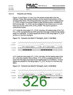
In E1 mode the rising edge of RL_SYNC should coincide with the leading edge
of the bit 1 of the first channel within a frame. If RL_SYNC is programmed as a
MF pulse then that edge should also be the leading edge of a multiframe. All
input signals are sampled on the falling edge of RL_CLK. as shown in the
following figure.
Figure 110 Receive Line Side E1 Timing(RL_CLK = 2.048 MHz)
RL_CLK(i)
RL_SYNC(i)
CHAN 31, FRAME 16
CHAN 0, FRAME 1
RL_DATA(i)
RL_SIG(i)
7
8
1
2
3
4
5
6
7
8
1
2
2
3
4
5
6
7
8
9
C
D
A
B
C
D
B
C
D
A
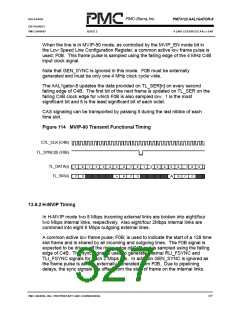
When the line is in MVIP-90 mode, as controlled by the MVIP_EN mode bit in
the Low Speed Line Configuration Register, a common active low frame pulse is
used; F0B. This frame pulse is sampled using the falling edge of the 4 MHz
C4Binput clock signal. C4B is also used to clock the data. The AAL1gator-8
samples the data provided on RL_SER[n] at the ¾ point of the data bit using the
rising edge of C4B. 1 is the most significant bit and 8 is the least significant bit of
each octet.
Note that GEN_SYNC is ignored in this mode. F0B must be externally
generated and must be only one 4 MHz clock cycle wide.
CAS signaling can be transported by passing it during the last nibble of each
time slot.
Figure 111 MVIP-90 Receive Functional Timing
CTL_CLK (C4B)
TL_SYNC(0) (F0B)
CHAN 31
CHAN 0
RL_SER(i)
RL_SIG(i)
7
8
1
2
3
4
5
6
7
8
1
2
2
3
4
5
6
7
8
9
C
D
A
B
C
D
B
C
D
A
PMC-SIERRA, INC. PROPRIETARY AND CONFIDENTIAL
325

 PMC [ PMC-SIERRA, INC ]