PM73121ꢀAAL1gator II
Data Sheet
PMC-Sierra, Inc.
PMC-980620
,VVXHꢀꢁ
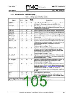
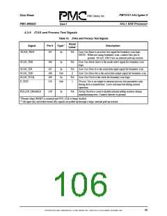
AAL1 SAR Processor
Table 8. T1/E1 Interface Signals (Continued)
Reset
Signals
Pin #
Type
Description
Value*
TL_SIG(7)
TL_SIG(6)
TL_SIG(5)
TL_SIG(4)
TL_SIG(3)
TL_SIG(2)
TL_SIG(1)
TL_SIG(0)
152
139
127
111
99
80
68
49
Out
0
Transmit Line Signal Bits 7 to 0 are the CAS signaling outputs
to the corresponding framer devices in the SDF-MF mode.
Maximum output current (IMAX) = 8 mA.
TL_MSYNC(7)
TL_MSYNC(6)
TL_MSYNC(5)
TL_MSYNC(4)
TL_MSYNC(3)
TL_MSYNC(2)
TL_MSYNC(1)
TL_MSYNC(0)
154
141
129
113
101
82
In
Out
In
NA
Transmit Line Multiframe Synchronization Bits 7 to 0 carry
multiframe timing information from the corresponding framer
devices. These signals do not need to indicate the start of each
and every multiframe. They can occur infrequently. Each time
one of these signals has an edge to indicate the start of a
multiframe, the AAL1gator II re-aligns the multiframe
according to where the edge occurred. Tie to ground if not used.
70
51
TL_SER(7)
TL_SER(6)
TL_SER(5)
TL_SER(4)
TL_SER(3)
TL_SER(2)
TL_SER(1)
TL_SER(0)
153
140
128
112
100
81
0
Transmit Line Serial Data Bits 7 to 0 carry the received data to
the corresponding framer devices. In the UDF-HS mode, only
line 0 is active.
Maximum output current (IMAX) = 8 mA.
69
50
RL_SIG(7)
RL_SIG(6)
RL_SIG(5)
RL_SIG(4)
RL_SIG(3)
RL_SIG(2)
RL_SIG(1)
RL_SIG(0)
162
149
137
125
109
97
NA
Receive Line Signal Bits 7 to 0 carry the CAS signaling
information from the corresponding framer devices in SDF-MF
mode. In UDF-HS mode, only line 0 is active.
78
66
RL_SER(7)
RL_SER(6)
RL_SER(5)
RL_SER(4)
RL_SER(3)
RL_SER(2)
RL_SER(1)
RL_SER(0)
161
148
136
124
108
96
In
NA
Receive Line Serial Data Bits 7 to 0 carry the receive data from
the corresponding framer devices.
77
65
ꢇꢄ

 PMC [ PMC-SIERRA, INC ]