PM73121ꢀAAL1gator II
Data Sheet
PMC-Sierra, Inc.
PMC-980620
,VVXHꢀꢁ
AAL1 SAR Processor
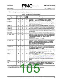
4.3.2 Memory Interface Signals
Table 7. Memory Interface Signals
Reset
Value*
Signal
Pin #
Type*
Description
MEM_DATA(15:10)
MEM_DATA(9:4)
MEM_DATA(3:0)
235-230
228-223
221-218
Bi
Z
Memory Data Bits 15 to 0 form the 16-bit wide data bus to external
memory.
MEM_ADDR(16:15)
MEM_ADDR(14)
MEM_ADDR(13:8)
MEM_ADDR(7:0)
215-214
211
208-203
201-194
Out
Z
Memory Address Data Bits 16 to 0 form the 17-bit wide address bus
to external memory. Pulled up with an internal resistor.
/MEM_OE
191
188
190
192
Out
Out
Out
Out
1
1
1
1
Memory Output Enable is an active low signal that enables the
SRAM to drive data. Maximum output current (IMAX) = 8 mA.
/MEM_WE(0)
/MEM_WE(1)
/MEM_CS
Memory Write Enable Zero is an active low signal for the low-byte
write. Maximum output current (IMAX) = 8 mA.
Memory Write Enable One is an active low signal for the high-byte
write. Maximum output current (IMAX) = 8 mA.
Memory Chip Select is an active low chip-select signal for external
memory. Maximum output current (IMAX) = 8 mA.
*Present when /RESET is asserted and SYS_CLK is being clocked.
4.3.3 T1/E1 Interface Signals
Table 8. T1/E1 Interface Signals
Reset
Value*
Signals
TL_FSYNC(7)
TL_FSYNC(6)
TL_FSYNC(5)
TL_FSYNC(4)
TL_FSYNC(3)
TL_FSYNC(2)
TL_FSYNC(1)
TL_FSYNC(0)
Pin #
Type
Description
155
142
130
114
102
83
In
NA
Transmit Line Frame Synchronization Bits 7 to 0 are the
transmit frame synchronization indications from the framer
devices in SDF-MF and SDF-FR modes. The lines originate
from the corresponding framer devices 0 to 7.
71
52
TL_CLK(7)
TL_CLK(6)
TL_CLK(5)
TL_CLK(4)
TL_CLK(3)
TL_CLK(2)
TL_CLK(1)
TL_CLK(0)
156
143
131
115
103
84
Bi
NA*
Transmit Line Channel Clock Bits 7 to 0 are the clock lines for
the eight T1/E1 lines. The bits clock the data from the
AAL1gator II to the corresponding framer devices. In the
UDF-HS mode, only line 0 is active. Depending on the value of
TLCLK_OUTPUT_EN and the CLK_SOURCE bits, these pins
are either outputs or inputs. If TLCLK_OUTPUT_EN is high,
these pins are outputs and the clock is sourced internally at
power up. This can later be changed by the CLK_SOURCE
bits.
72
54
Maximum output current (IMAX) = 8 mA.
* If TLCLK_OUTPUT_EN is high, the pins output the RL_CLK during reset.
ꢇꢃ

 PMC [ PMC-SIERRA, INC ]